I've decided to stop further designing/improving this amplifier.
It's time for some action!
All components are bought (Schuro / Germany), except:
- final amount of OPS devices
- final heatsinks from ELTIM (4x MODU Pesante Dissipante heatsinks 165mm/200mm)
In the attachments some of the final data is there.
It's time for some action!
All components are bought (Schuro / Germany), except:
- final amount of OPS devices
- final heatsinks from ELTIM (4x MODU Pesante Dissipante heatsinks 165mm/200mm)
In the attachments some of the final data is there.
Attachments
DC servo issues
Hi,
I'm using the schematic you can find below.
The DC-servo is non-inverting one, and coupled to the "back-side" of the diff input pair.
But, when switching on, the dc offset is raising instead of decreasing towards 0?
Has anybody an idea what causes this effect?
Thanks
Hi,
I'm using the schematic you can find below.
The DC-servo is non-inverting one, and coupled to the "back-side" of the diff input pair.
But, when switching on, the dc offset is raising instead of decreasing towards 0?
Has anybody an idea what causes this effect?
Thanks
Attachments
Hi,
I'm using the schematic you can find below.
The DC-servo is non-inverting one, and coupled to the "back-side" of the diff input pair.
But, when switching on, the dc offset is raising instead of decreasing towards 0?
Has anybody an idea what causes this effect?
Thanks
Does anybody has a clue wy the DC-servo has a reversed effect while it should not have?
Does anybody has a clue wy the DC-servo has a reversed effect while it should not have?
The DV servo can produce only a +- 30mV DC voltage at the inverting
input , wich amplified by the amp will produce about +-1V at the output.
If your amp , without the DC servo , has more than those +-30mV
input offset the DC servo will be unable to correct it.
Try reducing both R49/R48 to 22K while increasing C15 to 4.7uF.
If this doesnt work then check that Q1 is Vbe matched with Q2 ,
and the same for Q3 wich should be Vbe matched with Q4.
Thanks for the feedback,
I try your suggestion this evening, for now these are the values measured.
Without servo or dc-blocking cap I get:
1. +-0.55V DC offset at the output
2. this means +-20mV dc-offset at input
One more question, how do you calculate the 30mV (offset that DC-servo can produce?)
greetz
Thanks for the feedback,
One more question, how do you calculate the 30mV (offset that DC-servo can produce?)
greetz
Stupid question from me, I see it, 200K and 430Ohm make a voltage divider, with 15V supply, I can get max 30mV output offset.
The DV servo can produce only a +- 30mV DC voltage at the inverting
input , wich amplified by the amp will produce about +-1V at the output.
If your amp , without the DC servo , has more than those +-30mV
input offset the DC servo will be unable to correct it.
Try reducing both R49/R48 to 22K while increasing C15 to 4.7uF.
If this doesnt work then check that Q1 is Vbe matched with Q2 ,
and the same for Q3 wich should be Vbe matched with Q4.
I changed R49/48 to 22K, DC offset at output of amp decreases to 40mV and keeps hanging there. It takes about 30 seconds to drop to 40mV?
I'm not really satisfied with this? 40mV is to high is my opinion.
What can I do to improve this?
I changed R49/48 to 22K, DC offset at output of amp decreases to 40mV and keeps hanging there. It takes about 30 seconds to drop to 40mV?
I'm not really satisfied with this? 40mV is to high is my opinion.
What can I do to improve this?
40mV is indeed too high , but i cant say from where it originate.
The 30 seconds delay is due to the time constant of C14/R47
being too long.
Reduce one of the two components , let s say C14 , by a factor
of 5 to 10 , that is 2.2uF to 1uF, this will divide the delay by the same factor.
WOOHA,
The solution was again very simple;
The OP275 opamps which I was using in the DC-servo has a pretty high input bias current. I had some TL082 bifet opamps laying around, I swapped them out and..
==> DC offset is moving between -3mv and +3mv.
Greetz
Great news!!!!
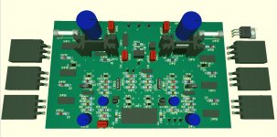
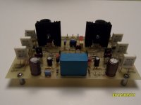
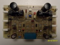
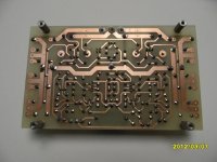
After blowing again 1 pair of output devices, I decided to make the final board layout to test further instead of having two boards connected to each other with wires. (two boards are; front-end + VAS, and Drivers and OPS)
Made the board yesterday with the toner transfer method and soldered all components on the board today. 1 pair of OPS will connected tommorow when all voltages and currents are ok.
Made the board yesterday with the toner transfer method and soldered all components on the board today. 1 pair of OPS will connected tommorow when all voltages and currents are ok.
Attachments
I would say that there are 4 versions of output devices that can be used in Power amplifiers.
BJT - silicon
BJT - germanium
FET - lateral
FET - vertical.
I believe that all 4 need to be approached differently at the design stage.
I further believe that one cannot simply swap between any of these types when an amplifier is designed to perform properly with only one of those types.
And I would not use the FETs in a sub amp. Just my experience. I don't understand why, but the FETs just don't have the same oomph. I drive my XLS's with an HCA 1200 and they are really happy. They were not as happy with bridged DH-220's or the single ST-140 I had. I tried several MOSFET plate amps, and regardless of the mega-watt ratings, they were dull.
And I would not use the FETs in a sub amp. Just my experience. I don't understand why, but the FETs just don't have the same oomph. I drive my XLS's with an HCA 1200 and they are really happy. They were not as happy with bridged DH-220's or the single ST-140 I had. I tried several MOSFET plate amps, and regardless of the mega-watt ratings, they were dull.
Than you never tried the Accusound 100 from ThelAudio
Stability testing
Today, I did some stability tests.
I used a 4Ohm resistor on the output of the amp with different caps up to 1µF.
The amplitude of the square wave is 0.15V.
The names of the pictures tells you the frequency and capacitor in parallel with the 4Ohm resistor.
The picture with the 4Ohm/1µ load shows a good damped behaviour in my opinion.
Can anybody help me to make a conclusion of these pictures.
Forgot the pictures: see next post
- Status
- This old topic is closed. If you want to reopen this topic, contact a moderator using the "Report Post" button.
- Home
- Amplifiers
- Solid State
- Amp design for subwoofer and wideband duty