I think that in order to disable the Rpar and Cpar of capacitors, you have to explicitly set them to zero. Otherwise, I think they have some default value.
But for Rpar of electrolytic caps, the manufacturer often gives something like:
"LEAKAGE CURRENT: 0.01CV, or 3uA, whichever is greater.".
So that means i = 0.01CV. But R = V/I. So Rpar = 1/(0.01C). C is in Farads.
----
For your slowness and convergence problems, the first thing I usually try is switching to the other solver, either normal or alternate, whichever one I wasn't using.
The second thing I try is reducing the time-step value. If you are setting the frequency of the input with a param statement, set the time step with something like {1/(5000*freq)}. If you see lots of spiky "glitches", often it means that the time-step is too large. (Unfortunately, you want it as large as it can be, to make the sim run faster. But you also want it as small as possible to make it more accurate. Like a lot of things, if you adjust it downward until the results stop changing, it should be good.)
One big gotcha can be high frequency resonances. Sometimes you can get runtime speeds of femtoseconds per second, if it converges at all! To defeat that behavior, you can try to make sure that everything has SOME resistance (for damping), i.e. no caps or inductors without ESRs. Sometimes you might have to insert small resistances into every trace (1 to 100 Ohms), to see where it stops the ringing. ALSO, always RF-filter (low pass) the inputs (and maybe add small resistors to the PSU lines), et al, and DON'T use signals that have super-fast edge times, especially not ideal square waves with zero rise and fall times. And even with reasonable rise and fall times, you still should LP filter them, so the corners aren't perfectly sharp. Also, sometimes you might have to blindly try inserting filters or snubber/terminator resistors, just to get a handle on where there might be HF ringing. If you can get even just a short bit of a plot, you can start clicking on different nodes and magnify the hell out of the end of the plot to try to see where there might be HF ringing that's starting to bloom.
Another thing that I have had to change, a lot, is Gmin. Usually I lower it but sometimes I have to raise it. You can also change the other parameters there, such as Trtol. Once you find what works, put it in a comment on your schematic!
Also, I always turn off all compression.
If you haven't joined the LT-SPICE USERS GROUP at yahoogroups.com, now is the time...
Cheers,
Tom
Last edited:
Thank you for the hints.
Progress, I think.
Reducing time step has brought my THD right back to the non parasitic values. Eg THD 20K = 0.000543%
Also changing Gmin to 2e-011 has stopped all source stepping.
Are the simulation results still valid?
Should I now go through with square wave inputs and check for ringing etc?
Man thanks
Paul
Last edited:
This parasitic stuff is very enlightening. I have had to change my compensation scheme to Edmonds DTMC which works very well. have changed the values and added back the RC network across the feedback resistor. Also, reintroduced the TIS emitter decoupling caps. End result has been a very clean closed loop plot, clean square waves and (I think impressive) PM = 104 degrees and GM = 20dB.
Gone is the AFEC as it made the THD worse with this alternative compensation.
Also, seen the need to improve the opamp PSU.
I would like to add some zeros to cancel some of the excess phase though. Not sure how to do this at present.
Gone is the AFEC as it made the THD worse with this alternative compensation.
Also, seen the need to improve the opamp PSU.
I would like to add some zeros to cancel some of the excess phase though. Not sure how to do this at present.
Last edited:
Looks like you're running into the same as I am: trying to find an optimal tradeoff between stability and THD ") I haven't been able to widen the phase margin of my VAS without detoriating THD at the same time. Wouldn't it be nice if we could increase the gain slope without additional phase
I haven't been able to widen the phase margin of my VAS without detoriating THD at the same time. Wouldn't it be nice if we could increase the gain slope without additional phase
I haven't been able to widen the phase margin of my VAS without detoriating THD at the same time. Wouldn't it be nice if we could increase the gain slope without additional phase Yes, its one of those triangular relationships Keantoken was on about. I noticed you were struggling with stability and THD with your VAS (which is beginning to make some sort of sense to me now you're adding output stages. There's no free lunch but there may be better value.
THD/Phase Margin/Gain Margin.
This is why I'm trying to understand how to use zeros to cancel out some of the poles. This may provide a way forward.
THD/Phase Margin/Gain Margin.
This is why I'm trying to understand how to use zeros to cancel out some of the poles. This may provide a way forward.
If only i had a ULGF. I'm utilizing an X buffer style input stage.
That was supposed to have been LTP.
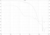
I would like to ask your opinion on this loop gain plot. This is from the full parasitic simulation. Would like your opinion on the shelving at around 200Mhz. Is this a problem?
The top line is the gain the bottom line is the group delay.
THD @ 20Khz is now 0.000200% (+/-35V out)
PM = 100 degrees / GM = 16dB.
Many thanks
Paul
The top line is the gain the bottom line is the group delay.
THD @ 20Khz is now 0.000200% (+/-35V out)
PM = 100 degrees / GM = 16dB.
Many thanks
Paul
Attachments
How did you extract phase margin from this simulation of closed loop performance? Phase margin is defined as 180 degrees minus (phase of (Vout/Vin) open loop) at ULGF, and people usually extract it from an open loop simulation.
The PM/GM came from a different simulation of the same circuit.
I've used the method described in Cordells book page 88 Fig 4.7. Where the loop is broken by a 1G inductor etc. Hopefully, I've done it correctly. I look for the point at which the gain falls back to 0dB after the peak.
The compensation scheme is now an adaptation of Edmond's DTMC which he claims had 95 degrees of PM in the MCP amplifier design of his.
Last edited:
I shall try this method. This may be the method I've seen that looks like hieroglyphics to me at present. Need to get an accurate measure of this then maybe I could trade PM for higher ULGF (or vice versa).
Do you think the shelving is a problem in the loop gain plot? It's not a peak as I've zoomed (focussed the sim) right in at that frequency.
Cheers
Paul
Do you think the shelving is a problem in the loop gain plot? It's not a peak as I've zoomed (focussed the sim) right in at that frequency.
Cheers
Paul
Interesting, just succeeded in getting the open loop gain example to work. It appears Bob Cordell's version isn't too far off (assuming the LTspice version is more accurate). Bob's version reckoned PM=100 degrees GM = 16dB. Ltspice version reckoned PM = 96 degrees and GM = 18dB.
Edit: I may have got my maths wrong... Is it 180 minus the reading at 0dB?
Edit: I may have got my maths wrong... Is it 180 minus the reading at 0dB?
Last edited:
Wasn't comparing apples with apples and my maths / logic was wrong. I had already traded PM for ULGF and had forgotten. Both methods give 87 degrees phase margin and 18dB of gain margin.
The question now is where next to go with the development. I have some minor PCB changes to make but what comes after?
Paul
The question now is where next to go with the development. I have some minor PCB changes to make but what comes after?
Paul
- Status
- This old topic is closed. If you want to reopen this topic, contact a moderator using the "Report Post" button.
- Home
- Amplifiers
- Solid State
- Amp design attempt number 2 (simpler)