Pass DIY Addict
Joined 2000
Paid Member
While I have some IRFP240's on hand Im interested what people think about using IRFP044's..
Some impressions of 044's vs 240's goes back to the conversations in the Aleph-X thread (from nearly a decade ago) in the context of heat, bias, etc. In short, the 044's have higher capacitance and offer "better" bass and midrange, but feature a "darker" top end. The 240's (with lower internal capacitance) were judged by a number of people to be somewhat better "balanced" across the audio spectrum.
Some impressions of 044's vs 240's goes back to the conversations in the Aleph-X thread (from nearly a decade ago) in the context of heat, bias, etc. In short, the 044's have higher capacitance and offer "better" bass and midrange, but feature a "darker" top end. The 240's (with lower internal capacitance) were judged by a number of people to be somewhat better "balanced" across the audio spectrum.
Aha! Cheers Iv'e read this somewhere before, Perhaps one day I will experiment with the 044's as well. Sounds similar to what happens when you parallel output devices
Loudthud
Thanks for your help , ill read the voltages and find out if both get hot and post back, Cheers!
......
I Can't get proper readings on the caps as I would have to remove the circuit board to get the probes underneath.
The Helps Very appreciated
Riki
look at schematic - cap is also connected to some other parts , and they're exposed
use tiny extending clips for DMM probes , or make your own hooks of thin solid core ; put them where needed , while amps is off
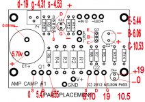
The reason I marked polarity on the diagram was just to make it crystal clear what the polarity was for novice builders. From the voltages posted it seem like something is turning on Q1 too hard. Q2 and Q3 look like they are functioning correctly. It's been my experience that when the IRF parts get static damage on the gate, the part becomes a very low resistance short. That doesn't seem to be the case here.
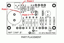
It seems like the problem is with Q4 or C3. Refer to the diagram attached below. What are the voltages at points 1, 2 and 3?
It seems like the problem is with Q4 or C3. Refer to the diagram attached below. What are the voltages at points 1, 2 and 3?
Attachments
It's normal for a delay of several seconds before the ACA starts to pass a signal. There will also be a thump when you turn the power off.
Try this: Adjust the pot so that point 1 is zero volts. That should turn Q1 off and the output voltage should go to about 16V. Take new voltage readings. My thinking now is that Q1 is bad.
Try this: Adjust the pot so that point 1 is zero volts. That should turn Q1 off and the output voltage should go to about 16V. Take new voltage readings. My thinking now is that Q1 is bad.
Pass DIY Addict
Joined 2000
Paid Member
I Can't get proper readings on the caps as I would have to remove the circuit board to get the probes underneath.
I always mount my devices a bit above the board so the component legs are exposed on the top side of the board. Zen has good advice as well!
It's normal for a delay of several seconds before the ACA starts to pass a signal. There will also be a thump when you turn the power off.
Try this: Adjust the pot so that point 1 is zero volts. That should turn Q1 off and the output voltage should go to about 16V. Take new voltage readings. My thinking now is that Q1 is bad.
Yep heard the thump and its not too bad
There's a funny noise on the speaker when i turned the pot down to make Point 1 = 0V, also happens on turn on, its hard to explain. a bit like a test tone sweep for a couple of seconds.
anyway now the readings are.
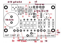
P2 = approx 0v maybe 1mv
P3 = 0v
16v and 0.4v on Q1
Shall I re-take the other readings ? ill do it anyway next
Cheers
Here the pic with the bias all the way down
Ill have a little trouble shoot myself in the morning

I Must say, I realy do like the sound of this amp and it may not be power house but the quality is there. well a bit distorted at half the bias it should be run at, but still great!
Once I have it going, will increase the bias higher and post results.
My ears are good and notice quality, like the difference between 320mp3 and original CD's/wav files but when I was younger I lost high frequency in my left ear.
so sad as I love music, perhaps Its fixable like this amp lol
Ill have a little trouble shoot myself in the morning

I Must say, I realy do like the sound of this amp and it may not be power house but the quality is there. well a bit distorted at half the bias it should be run at, but still great!
Once I have it going, will increase the bias higher and post results.
My ears are good and notice quality, like the difference between 320mp3 and original CD's/wav files but when I was younger I lost high frequency in my left ear.
so sad as I love music, perhaps Its fixable like this amp lol
Those voltage look like everything is as it should be, unless you have a wrong resistor or bad solder connection somewhere. From this point if you adjust the pot (slowly), the voltage at the output should fall and you should be able to stop when it gets near 10V. It may drift around slightly for a minute or two as things warm up.
Looks like we have 10v at drain of Q1, will further experiment tomorrow, what level can the bias be taken up on this thing ? My Sinks can handle it.
Id lower the Values of R1-R4 a little and then re-adjust .
When Its completed Im going to be using this amp in a car, 12v to 24v using dc-dc converter.
Id lower the Values of R1-R4 a little and then re-adjust .
When Its completed Im going to be using this amp in a car, 12v to 24v using dc-dc converter.
I'm starting to suspect that the ACA has some kind of latchup mode that you can get into when you first set the bias. Another builder had the same problem but he never followed up and didn't respond to my PM. When I connected two ACAs in balanced mode I had problems setting the bias when the inputs were connected to balanced floating (transformer) drive. The problem went away when I changed to balanced grounded drive. Maybe the input needs to be grounded or the pot set to one end or the other.
Because of the simplicity of the ACA, any changes affect the open loop gain and as a consequence, the spectral balance of the distortion. Changing R1-R4 is an easy way to increase the current, but I can't predict what that will do to the distortion. I have documented (in this thread) ways to get the measured numbers down, but I can't say it sounds any better. I like listening to mine with the feedback disconnected.
Because of the simplicity of the ACA, any changes affect the open loop gain and as a consequence, the spectral balance of the distortion. Changing R1-R4 is an easy way to increase the current, but I can't predict what that will do to the distortion. I have documented (in this thread) ways to get the measured numbers down, but I can't say it sounds any better. I like listening to mine with the feedback disconnected.
Hi,
My friend have bought heatsinks for ACA they are 190x70x30 Do you think they are sufficient?Few pics:
Regards,
Sachin
My friend have bought heatsinks for ACA they are 190x70x30 Do you think they are sufficient?Few pics:
An externally hosted image should be here but it was not working when we last tested it.
An externally hosted image should be here but it was not working when we last tested it.
An externally hosted image should be here but it was not working when we last tested it.
An externally hosted image should be here but it was not working when we last tested it.
Regards,
Sachin
Last edited:
- Home
- Amplifiers
- Pass Labs
- Amp Camp Amp - ACA

