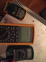
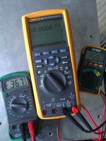
3rd meter needs to be connected to the speaker outputs...
Thanks for the reply! I spent over an hour today trying to figure that out. Couldn't find a pic or a post to save my life.
I had to shut it down and run over and pic up my laser thermometer, cooking again now, with the 3rd mm connected to the speaker terminals. The amp was off about 15 mins, switched it on, full power, no issue. I'm using a 4 amp slow blow fuse.
So after 1 hour this is what I have

I've adjust the offset as far as I can, no matter what voltage, the negative stays about 0.01 higher (numerically) and the closest I can get the offset is 0.2727.
Shooting my laser thermometer to the body of the heatsink, directly at the opposite side of the devices, I read 33-37C on the bottom row and 31-33C on the top row. (Cover on, fan on, interior of my condo is 26C) The top cover of the amp is 27.6C.
No noise, no vibrations, no hums, I can hear the cooling fan (with nothing else on in the condo) up to about 5 feet away.
Pretty excited that all the smoke has stayed put!
Are my numbers in range?
Odd that you can't get below 10mV DC offset.
Your DC offset is extremely high.
Is P3 set to the middle when you installed it? (did you measure it)
Dazed2, thanks for assisting. I centered P3 by meter before installing in board.
The next time I work on it (visitors flying in from mainland tomorrow for Turkey) I will start over, keeping an eye more toward zero offset, as I adjust from beginning. (Especially since I now know to connect to speaker terminal).
read tutorial more thorough
one DVM is for measuring one side ( say positive ) Iq
second DVM is for offset ( chase with other side biasing)
third DVM is for other side Iq , being there just in case for necessary Greenhorn confusing

Zen Mod, thanks for joining in and commenting! So much for me to learn and absorb, until I actually touch and see each step it's hard for me to understand what I'm reading.
What is the allowable range for the zero offset in relation to the difference between P and N readings? While adjusting I was more concerned with P and N matching as apposed to zero offset.
BigE , be precise , to not confuse him more
Iq - monitored as voltage across one source resistor ....... say in bracket of 400mV
output offset - as close to 0mV you can get
when output offset is zeroed , Iq of two (upper and lower) halves is practically the same ........ meaning - there is no amp's intention to push DC through speaker
so - to repeat - measure one half Iq and output offset - set them as per tutorial(s)
Iq - monitored as voltage across one source resistor ....... say in bracket of 400mV
output offset - as close to 0mV you can get
when output offset is zeroed , Iq of two (upper and lower) halves is practically the same ........ meaning - there is no amp's intention to push DC through speaker

so - to repeat - measure one half Iq and output offset - set them as per tutorial(s)
BigE , be precise , to not confuse him more
Iq - monitored as voltage across one source resistor ....... say in bracket of 400mV
output offset - as close to 0mV you can get
when output offset is zeroed , Iq of two (upper and lower) halves is practically the same ........ meaning - there is no amp's intention to push DC through speaker
so - to repeat - measure one half Iq and output offset - set them as per tutorial(s)
Practically is like 7-10 mv? I am using the matched fukushimas from the group buy.
output offset is measured with the input shorted and the output open.
The current passing through the upper half passes into the Output Node.
There are three routes out of that node. the upper feedback resistor/s, the lower feedback resistor/s and the lower mosFET.
If we assume the feedback resistor currents are zero then the lower mosFET current must be EXACTLY the SAME as the upper mosFET current.
You can measure the feedback resistor Vdrops and make a correction for non zero feedback currents.
Now using that info you should be able to measure the difference in source resistor values, whether you think they are matched or random selected.
The errors in the source resistor readings are due to errors in the source resistor values.
when buying the added value of pre-matched/selected resistors, the first thing I would do is re-measure to ensure they are as described.I see... so when purchasing 2 quads of matched resistors,when installing pairs of source resistors, should one select a resistor from one quad and the second resistor from the other quad ?
I have recently posted the method to do this twice over.
It is easy using comparison methods to confirm matching tolerance to better than 0.1%.
That is way more than what is required to measure the tolerances of multi-parallel output stage currents.
Thanks all for all the additional information.
I didn't understand, nor had read previously posted, that the source resistor matching was required. I used 5 watt mills, their spec is 1%. I didn't check them.
I will zero out P1 and P2 and start over, keeping the DC offset at zero, and report back what the difference between P and N is at that point.
Thanks!
Thanks all for all the additional information.
I didn't understand, nor had read previously posted, that the source resistor matching was required. I used 5 watt mills, their spec is 1%. I didn't check them.
I will zero out P1 and P2 and start over, keeping the DC offset at zero, and report back what the difference between P and N is at that point.
Thanks!
I understand that you are using the test points on the output boards for measuring your readings. The reading will be for the one device on that board. After adjusting everything also take a reading across the source resistor on the other device same board for comparison. Lets see what you get.
Congrats on your build.
Nash
Nash, thanks for the reply.
Good point, maybe before I start over I'll take a reading on all the resistors to see what I get.
Thanks for the congrats!
Art, thanks for taking the time to demonstrate the resistor calculation.this means the fan draws 48.7mA. By applying Ohm's law (12.3-10) / 0.0487= 47 Ohm
And dissipation will be V*I=0.11W so a 0.5W resistor will be fine
I had about 40 mins to try and rebalance the bias and offset before I had to run to the airport. After letting it run for about 20 mins to settle in I was able to get these numbers

I didn't have time to check the source resistors. Is the relationship between N and P to extreme, or tolerable? Now that I have zero offset.
Thanks!

I didn't have time to check the source resistors. Is the relationship between N and P to extreme, or tolerable? Now that I have zero offset.
Thanks!
- Status
- This old topic is closed. If you want to reopen this topic, contact a moderator using the "Report Post" button.
- Home
- Amplifiers
- Pass Labs
- Aloha F5 v3 Monoblock build