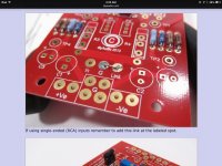
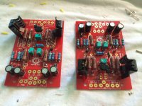
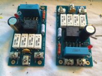
These are the PCB solder cups I used to enlarge the holes. The boards were drilled out, and the cups were soldered in on BOTH sides.
H9026-01 Harwin | Mouser
Sorry for the .ca link, but they are also available on digikey.
You must be careful to solder top and bottom of your connecting wires as the traces on the output boards are not all on the same side.
If you do use these cups on the FE board, you must ensure that the vias on the FE board are fixed,or else you will fry the jfets.
Last edited:
You can't just feed a balanced input in a unbalanced amp.
You can in this layout... but it's just going to be used as single-ended... I suggest just using unbalanced (RCA) connections.
You can in this layout... but it's just going to be used as single-ended... I suggest just using unbalanced (RCA) connections.
Forgive my ignorance , but how does that work? What happens to the other half of the signal?
Thanks for the info. I had seen these cups posted earlier. I feel uncomfortable drilling the boards, so I spent some time studying my options. With the way I posted I have good contact between the board and all of the wire, with only solder inserted into the equation.These are the PCB solder cups I used to enlarge the holes. The boards were drilled out, and the cups were soldered in on BOTH sides.
H9026-01 Harwin | Mouser
Sorry for the .ca link, but they are also available on digikey.
You must be careful to solder top and bottom of your connecting wires as the traces on the output boards are not all on the same side.
If you do use these cups on the FE board, you must ensure that the vias on the FE board are fixed,or else you will fry the jfets.
Thanks for shedding some light on the subject.You can in this layout... but it's just going to be used as single-ended... I suggest just using unbalanced (RCA) connections.
As I know basically zero about circuit design, some items go completely over my head. In the F5 Turbo article by Pass he mentions Patric and his "balanced" option. I understand that these boards are not laid out for balanced operation, but thought the board layout was designed to accommodate balanced input cables. My current preamp has both balanced and unbalance outputs. But my balanced cables are of higher quality than my RCA's.
What is the upside/downside to me staying with balanced inputs, as I have already gone this far?
Thanks for the info. I had seen these cups posted earlier. I feel uncomfortable drilling the boards, so I spent some time studying my options. With the way I posted I have good contact between the board and all of the wire, with only solder inserted into the equation.
Yes, but try to unsolder and resolder.
What is the upside/downside to me staying with balanced inputs, as I have already gone this far?
Nothing. Well, I guess you can short a couple of pins to make it unbalanced and use your existing cables.
SIL sockets fit the PCB.
The DCB1 had six holes at 0.1" centres and two 6pin lengths could be soldered straight in.
Allows one to plug in two jFETs to check the accuracy of matching at operating current and operating voltage.
Many PCBs use 0.1" hole centres.
SIL sockets accept upto 0.5mm diameter leads. 0.6mm can be forced in, but this may damage the spring contacts.
Thanks for shedding some light on the subject.
As I know basically zero about circuit design, some items go completely over my head. In the F5 Turbo article by Pass he mentions Patric and his "balanced" option. I understand that these boards are not laid out for balanced operation, but thought the board layout was designed to accommodate balanced input cables. My current preamp has both balanced and unbalance outputs. But my balanced cables are of higher quality than my RCA's.
What is the upside/downside to me staying with balanced inputs, as I have already gone this far?
in my case I used a balancing transformer to take the balanced signal to single ended. http://www.jensen-transformers.com/datashts/11p1.pdf
You can see it in one of the pics.
My current preamp had RCA's only, then I added a pair of output transformers and XLR's for balanced amps. So with my current setup it's no problem running RCA's only.in my case I used a balancing transformer to take the balanced signal to single ended. http://www.jensen-transformers.com/datashts/11p1.pdf
You can see it in one of the pics.
But the future?
A little update. I have finished installing the N and P boards on both sides of both monoblocks. The misc straggling parts have come in and I'm ready for final assembly.
Here is the DIY power supply boards. Since I'm tight on space I am using monolithic bridges and split and stacked the board. One stack for each monoblock. I have a pair of jumpers to tie the grounds together.
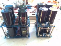
Here is the DIY power supply boards. Since I'm tight on space I am using monolithic bridges and split and stacked the board. One stack for each monoblock. I have a pair of jumpers to tie the grounds together.

AMB E24 start circuit board for the push off/on button. I have to remove a cap a resistor and the diode as the board is designed for 12 A/C and I have a dedicated 12 VDC supply.
This board is tiny, like 1" x 2". It has a overheat feature that I'll be taking advantage of. I mounted a snap disk to the middle of the upper heatsink that will trip (open on rise) at 75 deg C.
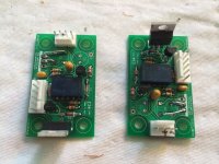
This board is tiny, like 1" x 2". It has a overheat feature that I'll be taking advantage of. I mounted a snap disk to the middle of the upper heatsink that will trip (open on rise) at 75 deg C.

- Status
- This old topic is closed. If you want to reopen this topic, contact a moderator using the "Report Post" button.
- Home
- Amplifiers
- Pass Labs
- Aloha F5 v3 Monoblock build
