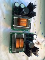
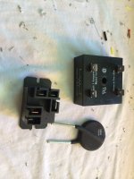
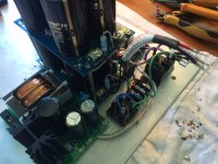
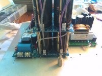
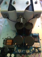
Now that I have all the individual boards and devices assembled (parts just arrived for the speaker protection boards, so a few days before I get to that) I am starting on the wire connections. Due to the design of my chassis and part layout I need to design the connections for ease of assembly/disassembly and to isolate circuits for a step by step startup sequence. It seems the norm is to build and check as you assemble. But since this is my first big amp project I want to make sure everything fits and wire length is minimized first.
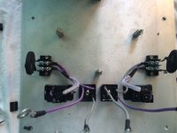
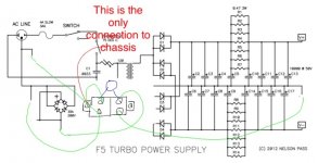
In the F5 Turbo paper by Nelson drew a circuit using a CL60 and a 35 amp rectifier bridge for ground loop isolation. So I have a 2 leg terminal block that I'm using one mounting screw for earth and one for ground. I plan on a connection from the ground side going to the neutral bar of my large cap bank to make the star ground.
Here is a pic of the ground loop circuit assembly, one for each monoblock. (CL30 in pic, CL60's not in hand for pic) do I have this correct?
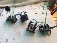

I'm a little confused on the correct layout to connect the secondaries to the cap bank via the bridge rectifier. In the schematic by Nelson of the power supply (F5t) he shows one leg of each secondaryto the rectifier and the other leg of each secondary going to the common neutral of the cap bank.
Pics of the DIY assembly board and a couple other builds with pics, show both legs of each primary going to a monolithic bridge each.
Is there a reason for the difference?
Pics of the DIY assembly board and a couple other builds with pics, show both legs of each primary going to a monolithic bridge each.
Is there a reason for the difference?
The reason is not aparent to me but I have built both and both work well. NP was specific about using the same rectifiers for the F5t builds in this higher power PSU design with the (created or built in) center tap (the PSU for the F5t builds) but maybe he is just using up what is at hand  He buys in Large quantities...or maybe he just likes the diodes!
Thanks for the reply!The reason is not aparent to me but I have built both and both work well. NP was specific about using the same rectifiers for the F5t builds in this higher power PSU design with the (created or built in) center tap (the PSU for the F5t builds) but maybe he is just using up what is at handHe buys in Large quantities...or maybe he just likes the diodes!
Since I only know a little more than following pictures I'm going to follow what I've seen and connect each pair of secondaries to its own monolithic bridge.
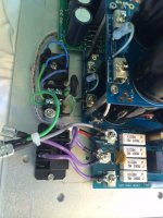
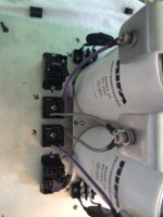
Starting to screw all the boards etc to the chassis and wiring up. Here is the soft start, relay for the on/off, grounding, and power to the 12vdc power supply board. Everything look ok so far?
View attachment 448160
Now test it before connecting anything else.
Infact test the soft start by itself and the slow charge by itself then hook it up to the cap bank and measure and make sure you have correct voltages etc.
Dazed2 thanks for looking and commenting.Now test it before connecting anything else.
Infact test the soft start by itself and the slow charge by itself then hook it up to the cap bank and measure and make sure you have correct voltages etc.
My plan is to build and wire the amp complete first. That way I can get most of the fabrication done before I start testing each "system". I have removable connections on at least one side of each item. When time comes to start lowering up I will disconnect everything from each other and start checking one by one.
I have a tendency to take shortcuts at the end of a project. So I have learned its best for me to complete each step as I go, or I might leave too many loose ends!
Rod Elliott states this additional nugget: "Never route an earth wire to the main (star) earthing point on a chassis in such a way that it forms a partial (or full) turn around a transformer. It is better to relocate either the star earth point or the transformer to ensure that no earth conductor can create a partial turn. There may often be conflicting requirements, but there is usually no reason that proper earthing for minimum hum and maximum safety should be mutually exclusive. Both are important, and both must be accommodated in the final design."
AFAIK, ground loop breakers ought to terminate at the same place that the safety earth is located. It looks like you will have some distance between the two.
No.
minimise the impedance of each connection.
PE gets connected to Chassis right at the mains incomer.
Mag gets connected to Chassis at the MAG location.
PE and MAG can be many inches apart and are in most amplifiers.
Thanks for reviewing my pics and commenting!
So this is a little over my head. Here is a pic with notes to show more specific how I have it wired. The wire from the power supply to the other side of the CL60 is kind of hidden behind the leg of the CL60, hence my red scribbles!
This is the only place I have connected to earth and ground as shown in pic. I'm about to connect the ground of the transformer. I assume I need to connect to the same lug as I connected the power supply?
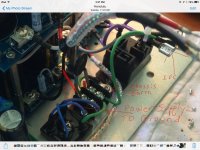
I have both amps built and wired, less final exterior finish and final connections to FE board.
Starting the power up phase now.
Started with my 12vdc power supply. I had a jumper wrong and was getting 8vdc, made the change and now getting 12.3vdc.
I made some wrong assumptions early on and didn't think through some of my control circuit plans. I'm using the AMP.org board for the momentary switch. I planned on using my larger 12vdc power supply for this but with 3 relays and a timer the AMP board isn't designed for this load. So waiting on the small matching power supply board and parts to build it. Then the small transformer can bring on the larger power supply that supplies the fan, and timer and relays to drop out the MS35's.
I've bypassed the switch and using the variac to power on/off.
I have a small 5 amp variac to help.
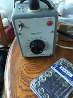
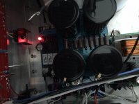
First test up is the soft start (BTW I'm disconnection everything down stream of each step) relays engage, red led comes on and getting 117 v AC (same as wall outlet)
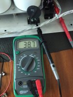
Next up is the transformer. I slowly increased power up to full voltage, no issue. Let it settle a few mins and I'm getting 38.7 v AC on the secondaries. Turned it back off, waited 5 mins, then switched it back on at full 117 volts, again no issue, soft start seems to be doing its job.
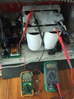
Then checked the power through the bridge rectifiers and getting -52.8 on one pair and +53.1 on the other pair.
Then after a couple min wait after power down I connected the 4ea 82,000 Rifa caps. Again, I slowly powered up with the variac, back up to the 117 volts, no issue. Powered down, waited 5 mins, then full on power via the variac switch.
I guess the soft start and slow charge circuits are working so far.
Now on to the DIY power supply board check.
See any issues yet?
Starting the power up phase now.
Started with my 12vdc power supply. I had a jumper wrong and was getting 8vdc, made the change and now getting 12.3vdc.
I made some wrong assumptions early on and didn't think through some of my control circuit plans. I'm using the AMP.org board for the momentary switch. I planned on using my larger 12vdc power supply for this but with 3 relays and a timer the AMP board isn't designed for this load. So waiting on the small matching power supply board and parts to build it. Then the small transformer can bring on the larger power supply that supplies the fan, and timer and relays to drop out the MS35's.
I've bypassed the switch and using the variac to power on/off.
I have a small 5 amp variac to help.

First test up is the soft start (BTW I'm disconnection everything down stream of each step) relays engage, red led comes on and getting 117 v AC (same as wall outlet)

Next up is the transformer. I slowly increased power up to full voltage, no issue. Let it settle a few mins and I'm getting 38.7 v AC on the secondaries. Turned it back off, waited 5 mins, then switched it back on at full 117 volts, again no issue, soft start seems to be doing its job.

Then checked the power through the bridge rectifiers and getting -52.8 on one pair and +53.1 on the other pair.
Then after a couple min wait after power down I connected the 4ea 82,000 Rifa caps. Again, I slowly powered up with the variac, back up to the 117 volts, no issue. Powered down, waited 5 mins, then full on power via the variac switch.

I guess the soft start and slow charge circuits are working so far.
Now on to the DIY power supply board check.
See any issues yet?
After using a standard lightbulb to drain the voltage from the large cap bank, I connected the DIY power supply board. The PSU is not connected to the FE board yet. Again, using the variac, I slowly powered up the amp. Lucky again, no issues presented themselves yet!
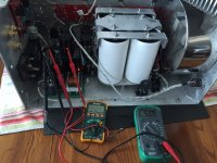
-50.7dcv on one leg and +50.9vdc on the other. Ending up pretty close to my 50 volt per rail goal.
After powering down I waited till 50% of the voltage bled off and powered back up, full voltage, no issues.
That's enough for today, going to wire in the FE board tomorrow and see about powering up the final step.
Last edited:
First monoblock cooking right now! So far so good.
I set the initial bias as seen in the two meters, close to .3volts. Been cooking for about 20 mins so far.
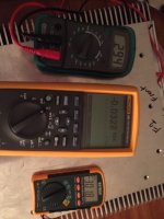
So question to make sure I'm actually connected correctly.
P board and N board mm's connected to TP1 and TP2.
3rd mm connected to TP1 of each P and N board.
I set the initial bias as seen in the two meters, close to .3volts. Been cooking for about 20 mins so far.

So question to make sure I'm actually connected correctly.
P board and N board mm's connected to TP1 and TP2.
3rd mm connected to TP1 of each P and N board.
- Status
- This old topic is closed. If you want to reopen this topic, contact a moderator using the "Report Post" button.
- Home
- Amplifiers
- Pass Labs
- Aloha F5 v3 Monoblock build
