Thank you Mr Pass.
I guess it has been sometime (since 2004) where most of the AX100 build activity was most active; and read some of the thread from the past. I have attached the schematics from Blitz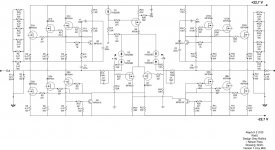 and expected voltages from Netlist
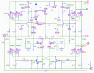 - they were in the another AX100 thread http://www.diyaudio.com/forums/pass-labs/27319-help-needed-firing-up-aleph-x100-6.html. I am currently reading the postings and implementing some of the suggestions - going through the solder joints, wirings, replace the IRFP9610 and MPSA18.
I guess it has been sometime (since 2004) where most of the AX100 build activity was most active; and read some of the thread from the past. I have attached the schematics from Blitz
 and expected voltages from Netlist
 - they were in the another AX100 thread http://www.diyaudio.com/forums/pass-labs/27319-help-needed-firing-up-aleph-x100-6.html. I am currently reading the postings and implementing some of the suggestions - going through the solder joints, wirings, replace the IRFP9610 and MPSA18.
Hello,
I am a newbie to the DIY audio field and am interested in building a version of the aleph-x amplifier.
Given that the wiki is no longer availible, is this thread the best source of information?
Also, what is the recommended source for obtaining a PCB?
Thanks for your help,
Matt
I am a newbie to the DIY audio field and am interested in building a version of the aleph-x amplifier.
Given that the wiki is no longer availible, is this thread the best source of information?
Also, what is the recommended source for obtaining a PCB?
Thanks for your help,
Matt
Pass DIY Addict
Joined 2000
Paid Member
Hi Matt,
Have a look at my Aleph-X web page: PassDIY Aleph-X 100w amplifier construction notes, parts, & mosfet matching
I have a great deal of information there and a PDF copy of the Aleph-X wiki before it disappeared from this site. I am just now completing a set of 100wpc Aleph-X amps myself.
Don't know how many of the original PCBs are floating around out there, but somewhere here on this forum was a post about one that was wired in point-to-point fashion without a PCB.
Happy Reading!
Eric
Last edited:
In a gesture of shameful self-promotion - here is the referenced thread:
http://www.diyaudio.com/forums/pass-labs/73543-ax100-100w-aleph-x-monoblocks.html
A PCB is not required. Save yourself some money and use perf board. It will also let you adjust the position of components and connection points to better match up with the rest of your amps physical layout.
My amps still sound fantastic after years of use. Be encouraged.
Happy New Year and Good Building to you.
Graeme
Hey Eric,
Thanks for the response. I will give your site a good run over and see what I can come up with.
Thanks for posting the PDF. I have looked through your site briefly before and found the links and information quite helpful.
I was wondering if you please offer any about what to do about the pcb. Should I try to make my own, or do you know of a way to obtain a set?
Thanks again for your help.
Matt
Pass DIY Addict
Joined 2000
Paid Member
Hi Matt,
I looked back through my rather large collection of parts and supplies and found an extra set of v1.0 boards from the original group purchase back in 2002 or so (the same board pictured on my web page). I would be happy to pass them along to you in exchange for a $25 donation to help support DIYAudio.com. I'll get a hold one of the moderators to see how to make that happen.
Eric
Pass DIY Addict
Joined 2000
Paid Member
Hello Matt,
Certainly above and beyond the call! I received your mailing address and I'll get the boards in the mail to you shortly - don't know if it will be tomorrow or not as they are calling for 4" of snow overnight.
If you have any questions, please let me know! I've begun updating my web page again this week, so it is more complete now. I think everything that you need is there.
Eric
Input Capacitors
Can't remember if i posted before about this, but...
I was going to use 8.2uf capacitors to connect the XLR socket to the PCB (simply because i have enough of them) - is this big enough (thinking of premature LF/HF rolloff) or should i go with 10uf instead?
(I am using 10K input resistors for R18/R19, the center point of which goes off to the gates of the IRF9610's, so i'm guessing my input impedance is about 10K)
What are the differences in rolloff between cap values (sorry - i should know this, but electronics college was 20 years ago and i haven't worked in the electronics industry for 18 years) - if someone would be so kind as to post the formula i'll do the calculations)
Or would i be better of changing the input impedence as a cheaper option? (in which case i'd welcome suggestions on what values to change to).
The formulae for roll-off frequency is F=(1/(2*pi*R*C)) where pi = 22/7, R = Resistance, C=Capacitance.
If you know that your input source is DC free (i.e. pre-amp has the output capacitor), it is not necessary to have the input cap for the power-amp.
I have used 2.2uf MKP10 PP caps with 10nf PP bypass caps and it sounds great. I would assume 8.2uf gives better roll-off frequency.
BTW - I am still struggling with my AX build but took some time-off to enjoy AJ that was recently constructed. I have only one-side of the AX's CCS (Q6) heating-up but GS (Q11) is stone cold even thought there source resistor for Q11 shows 0.4V; voltage across R23 is 8.3V and 0V across R25. Q1 and Q4 does not have any voltage across the source resistors. I have double checked the circuit and seems OK - could be missing something somewhere. Any suggestions for trouble shooting?
Pass DIY Addict
Joined 2000
Paid Member
OK, so my new 100w AlephX monobloc is completed and I'm about the flip the switch for the first time. The power supply has been tested and is working. I have 66,000uf then a 0R2 50w resistor then 220,000uf per rail. There is a CL-60 thermistor in series with each leg of the transformer primary and the power supply produces just over 24v.
The output stage is wired and has been double and triple checked for correct wiring. I am using 12 mosfets per channel and have carefully matched mosfets (to the 0.003v level) and the input differential (to the 0.001v level). The input differential is electrically insulated and mounted directly to the heat sink above the output mosfets for increased thermal stability.
I understand the process of biasing and adjusting any potential DC offset. What else should I be looking for as I power things up?
Thanks!
Eric
Pass DIY Addict
Joined 2000
Paid Member
A few pictures of my progress. This is the first of 3 identical monoblocks that I am building. I copied William's 100w design with 22v rails and ~7A bias.
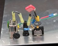
First up, the AC inlet: 6A EIC filter, fuse, heavy-duty switch with cap bypass, and a CL-60 thermistor on each leg of the transformer primary.
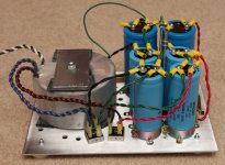
The completed power supply: 750VA from Victoria Magnetics with dual 18v secondiares. Each rails is constructed from run of the mill bridge rectifiers, two 33,000uF caps in series, 0.2 ohm 50w resistors, followed by a 220,000uF cap (thanks, Peter!). Since my wire is 14g, I used dual runs for all power supply connections. Unloaded, the PSU delivers 24.4v on each rail. I'm hoping it drops by a few volts when its fully loaded down since my big caps at the end are only rated to 25v.
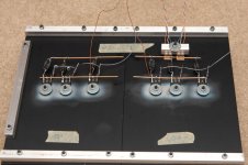
Each side of the chassis is made from two 10" lengths of extrusion #MM1165 from M&M Metals strapped together with 1/2" square bars of aluminum. I used 400 grit sandpaper and a little WD40 to smooth the areas where the mosfets are mounted. This made a big difference in the smoothness of the surface! They mosfets are insulated with Bergquist Sil-Pad 1500ST and held down with big washer to spread the mounting force (gently hand tightened). Spring-style lock washers were used between the big washer and the nuts on each mosfet.
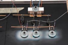
The differential pair for the front end is mounted side-by-side just above the center mosfet on the heat sink. They are insulated with silpads and clamped to the heat sink with the short piece of 1/2" aluminum barstock. Hopefully, this will help them stabilize quickly and track identical temperatures to minimize DC offset at the outputs. The front end was matched at operating voltage and current for 15 minutes and the two transistors track voltages to within 0.0001 of one another.
Here is the almost completed chassis. As you can see, I've not yet wired the signal in or speaker out terminals.
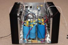
Finally, I installed a small piece of scrap aluminum as a step to help keep noise from the power supply away from the circuit board. All wiring is complete except signal in and speakers out. The thermistor on top of the cap in the bottom of the image connects the PSU ground to the AC ground. It is intended to prevent ground loops, yet let current flow should it need to.
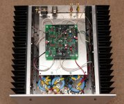
I'm simultaneously excited and hesitant to flip that switch for the first time. I've been over everything at least three times looking for errors and everything looks good.
First up, the AC inlet: 6A EIC filter, fuse, heavy-duty switch with cap bypass, and a CL-60 thermistor on each leg of the transformer primary.

The completed power supply: 750VA from Victoria Magnetics with dual 18v secondiares. Each rails is constructed from run of the mill bridge rectifiers, two 33,000uF caps in series, 0.2 ohm 50w resistors, followed by a 220,000uF cap (thanks, Peter!). Since my wire is 14g, I used dual runs for all power supply connections. Unloaded, the PSU delivers 24.4v on each rail. I'm hoping it drops by a few volts when its fully loaded down since my big caps at the end are only rated to 25v.

Each side of the chassis is made from two 10" lengths of extrusion #MM1165 from M&M Metals strapped together with 1/2" square bars of aluminum. I used 400 grit sandpaper and a little WD40 to smooth the areas where the mosfets are mounted. This made a big difference in the smoothness of the surface! They mosfets are insulated with Bergquist Sil-Pad 1500ST and held down with big washer to spread the mounting force (gently hand tightened). Spring-style lock washers were used between the big washer and the nuts on each mosfet.

The differential pair for the front end is mounted side-by-side just above the center mosfet on the heat sink. They are insulated with silpads and clamped to the heat sink with the short piece of 1/2" aluminum barstock. Hopefully, this will help them stabilize quickly and track identical temperatures to minimize DC offset at the outputs. The front end was matched at operating voltage and current for 15 minutes and the two transistors track voltages to within 0.0001 of one another.

Here is the almost completed chassis. As you can see, I've not yet wired the signal in or speaker out terminals.

Finally, I installed a small piece of scrap aluminum as a step to help keep noise from the power supply away from the circuit board. All wiring is complete except signal in and speakers out. The thermistor on top of the cap in the bottom of the image connects the PSU ground to the AC ground. It is intended to prevent ground loops, yet let current flow should it need to.

I'm simultaneously excited and hesitant to flip that switch for the first time. I've been over everything at least three times looking for errors and everything looks good.
Last edited:
Pass DIY Addict
Joined 2000
Paid Member
- Home
- Amplifiers
- Pass Labs
- Aleph-X builder's thread.