easy to try both ways
give me pic - to see physical layout of input ( RCA + XLR , or you have just RCA )
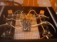
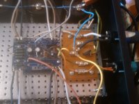
Horrible photo but should do the trick, doesn't have any fancy input. (I'm using XLR)
As it is now I'm using -21 db H-pad attenuators before the amp so turning it into a power buffer would probably be ideal, but for that BA1 might be more suited?
// Olle
Attachments
While preparing for Aleph-J build, I have some questions about the circuitry.
1. On the original schematics, there is "4.3V" marked for Vce of Q3 and Q4. I know those voltages are not fixed. Vce for Q3 is controlled by voltage across R7. But how about Vce for Q4? Is it simply formed by voltage across R16 plus VGS of the chosen device for Q5?
2. Compared to Aleph Current Source in Zen-V2, R27 was added here. My understanding for R27 is that it provided some extra current for R15. The extra voltage developed across R15 then reduced the voltage across R16, hence lower bias current. Is this correct? If so, is this the only function for R27? Does is affect anything else, performance wise?
Thanks,
4.3V is just an approximation of the voltage required to turn on the output devices. The voltage across Q4 is determined by the current through it and therefore R25 and R26. This current is set by the operating point of Q4's base. At idle it is determined by the R27/R15, R16 voltage divider. Current through R16 is the primary factor. Of course it is modulated by input through R24 when playing music.
Your understanding of the impact of R27 is basically correct. The higher the value of R27, the higher the bias. Rather than think of R15 current reducing R16 voltage, I think of it as changing the set point within the current source feedback loop. The voltage across R15 + R16 is equal to the Vbe of Q4 required to maintain ~4.3V Vce on Q4. Changing R15 voltage changes the operating point of Q4 to result in a different Q5 current and therefore voltage across R16.
Changing bias changes the sound character of the amp. Audibility depends on a number of factors.
Hope this helps.
just put series resistor in each balanced input leg
with additional 220K in each leg you'll have ~ unity gain
Ah, might as well ask this also since you probably know
")
Does series resistors on the inputs affect impedance matching and possibly distortion or is the only effect less input signal? For the sake of it say I put a 1M, or maybe even 10M series resistor on both XLR+ and -, would the only result be less input signal or would amplifier distortion also rise?
// Olle
Hello
I am looking for a while at aleph(3,30,J) schematics and topics around here and want to build one of them.I`ve decided about the J but the 3 will have more output poker on my 4ohm Dynaudio X12(Aleph 3 has 60W on output at 4ohm load and the J has only 40W) but the J has a more rafinate sound .The speakers have only 86dB and my room has 18 square metters.I am wondering if the power difference will be significant.Can i get 60W from the J and at which % of distotion?
I want to build 2 monoblocks each with 500va transformer(what voltage should i get them?) and for filtering 5x PANASONIC|ECOS1VA223EA|CAPACITOR, 22000UF, 35V | Farnell România per rail (20 pieces for 2 channels).Are they good?
For heatsinks I want to use something from TRE S SRL - dissipatori di calore, profili in alluminio estruso, lavorazioni su dissipatori di calore, sistemi di dissipazione del calore, estrusi per dissipare saw the site few posts earlier and I was thinking at one of these
TRE S SRL - details for heat sink it has 0.1078 deg C / W 1 metter long
and
TRE S SRL - details for heat sink it has 0.1082 deg C / W 1 metter long
thermal coeficient was calculated with Rodd Eliott's Heatsink thermal rating calculator http://sound.westhost.com/heatsink.zip can anyone check if I calculated corectlly?
I want to split 1m of heatsink in to 4 pieces of 25 cm each and mount them on the sides of each amp.Which of those two heatsinks do you reccomend?
Thanks for the moment
Last edited:
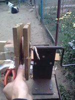
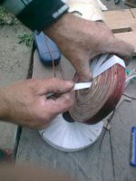
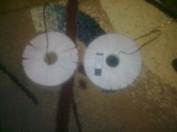
i have started with building the power supply filter coils.i have hand wounded them with Ø2mm copper wire and after a day of work i have finished 2 of them for one monoblock.now my problem is that one coil has 2.35mH and the other has 2.44mH(the bigger one has one extra layer).would there be any problem if one is bigger than the other ? should i get off the extra layer? or should i bring both coils to same schematic value of 2.2mH?
please help me so i could continue with building the last 2 coils for the other monoblock
thank you
please help me so i could continue with building the last 2 coils for the other monoblock
thank you
Attachments
i have started with building the power supply filter coils.i have hand wounded them with Ø2mm copper wire and after a day of work i have finished 2 of them for one monoblock.now my problem is that one coil has 2.35mH and the other has 2.44mH(the bigger one has one extra layer).would there be any problem if one is bigger than the other ? should i get off the extra layer? or should i bring both coils to same schematic value of 2.2mH?
please help me so i could continue with building the last 2 coils for the other monoblock
thank you
We're talking 3% difference between the 2 here..... your transformers and capacitors have probably 5 times more tolerance than that.
In any case, the inductor are here to lower down the ripple, so they don't need to be matched at all. They need to have enough inductance to do the job... 2.44 mH is actually even BETTER.
and to go even further.... most people here are happy with a small R in their power supply (CRC) instead of the 2 L (CLCLC)... which is technically (theoretically) inferior, but just sufficient for the job.
The Zen series started with just a C ....
Ho and by the way... which schematic are you using that specifies 2.2mH in the power supply ???
The Zen series started with just a C ....
Ho and by the way... which schematic are you using that specifies 2.2mH in the power supply ???
Last edited:
Sure enough, the CLC is technically better (more elegant I would say), and you can play with PSU designer to fine tune everything which is fun.... But one thing that makes me happy with the CRC is the original Firstwatt Aleph J is using them!In simulations I found that a 0.1R resistor and my 0.29mH inductor with DCR= 0.082ohms passed the same amount of 50Hz but the CLC had lower output impedance and much improved levels of 50Hz harmonics.
Another reason is.... "I have plenty of them" (they only sell them in bags where I live).
Yeah, they appeal to my sense of better and best ;P
It took a few sims to determine what was gonna be the best setup... does the output impedance matter to the Aleph circuit? I've built a heavy CLC PSU for my F5 (hence my decision ultimately to use a smaller inductor to reduce output impedance at cost of ripple) and I plan to use the same PSU for a number of other amps while testing, including Aleph J's which are next on my list.
It took a few sims to determine what was gonna be the best setup... does the output impedance matter to the Aleph circuit? I've built a heavy CLC PSU for my F5 (hence my decision ultimately to use a smaller inductor to reduce output impedance at cost of ripple) and I plan to use the same PSU for a number of other amps while testing, including Aleph J's which are next on my list.
Aleph J - power supply
Could you be so kind and post schamatic diagram of power supply. Everybody pay the most attention on amp itself diagram but nobody seems to care about powes supply
Dear Mr Pass,Here it is again.
Could you be so kind and post schamatic diagram of power supply. Everybody pay the most attention on amp itself diagram but nobody seems to care about powes supply
Would it be ok to use 22k and 220k instead of 22k1 and 221k on the input of the J ? Thanks.
These would be R1; R2 and R3 on the schematic.


- Home
- Amplifiers
- Pass Labs
- Aleph J Schematic