> another brilliant idea .......
Let's see ......")
Diff pair first.
Drain resistor is lowered to 160R.
R3 + eq. source resistance of the J109 (= 1/Yfs) is about 80R. So your 1st stage now has a gain of 2, instead of the original (1k/40R=) 25.
Of course you can parallel 12x LU1014s to get it back.
But you may also choose to use 7x bipolars (min 3W each) below Q1 and change the diff pair drain back to 1k. That would be in principle the same as using a 25W 4V5 Zener below Q1 (post #220).
Seems like 2x J511 at diff pair drain is still the front runner ......
Minor details; but that is also where the devil is.
Patrick
Let's see ......
Diff pair first.
Drain resistor is lowered to 160R.
R3 + eq. source resistance of the J109 (= 1/Yfs) is about 80R. So your 1st stage now has a gain of 2, instead of the original (1k/40R=) 25.
Of course you can parallel 12x LU1014s to get it back.
But you may also choose to use 7x bipolars (min 3W each) below Q1 and change the diff pair drain back to 1k. That would be in principle the same as using a 25W 4V5 Zener below Q1 (post #220).
Seems like 2x J511 at diff pair drain is still the front runner ......
Minor details; but that is also where the devil is.
Patrick
EUVL said:...............
Minor details; but that is also where the devil is.
Patrick
now you are talkin' ..............

EUVL said:> now you are talkin' ..............
No, I am helping you along with your mental jogging.
exactly .
Once you have solved this one (Vgs) -- elegantly, may I add, I have the second problem lined up for you (capacitance & stability).
Patrick
hehe....... there is a long way to looking at LU data ............. maybe I'll finally look for it in my puter .....
ha!
I found it.....
intentionally used time for EDIT:
Man responsible for that fine graph is my grumpy fellow from Germany ........... his nick is starting with E and finishing with L ........ four letters ..........third letter is V ,second one is U

Attachments

> why you think that capacitance will be issue more than with plain IRF?
Finish the Vgs jogging first before you start another one.
By the way, I don't think; I know.
One hint : a cascode LU1014 has WAY too little capacitance as seen by the diff pair source resistor compared to uncascoded IRFP240s.
Patrick
Finish the Vgs jogging first before you start another one.
By the way, I don't think; I know.
One hint : a cascode LU1014 has WAY too little capacitance as seen by the diff pair source resistor compared to uncascoded IRFP240s.
Patrick
EUVL said:> "I have a cunnin' plan ........ "
See post #228, 231.
Patrick
"let it bleed" .......and it will be good enough
so ?
gimme your proposal
Zen Mod said:naah.......
"I have a cunnin' plan ........ "
drek.........
1V1 in wrong side...........
> gimme your proposal
Already did.
http://www.diyaudio.com/forums/showthread.php?postid=1355853#post1355853
Keep the 1k (820R) drain resistors connected to -24V.
Connect an additional J511 from the J109 drain to -34V.
The J511 drains the 4mA bias away to give you 0V across the 1k resistors, AND gives you PSRR between -24V & -34V rails.
I was hoping Nelson or Grey might have better ideas.
Patrick
EUVL said:> gimme your proposal
Already did.
http://www.diyaudio.com/forums/showthread.php?postid=1355853#post1355853
Keep the 1k (820R) drain resistors connected to -24V.
Connect an additional J511 from the J109 drain to -34V.
The J511 drains the 4mA bias away to give you 0V across the 1k resistors, AND gives you PSRR between -24V & -34V rails.
I was hoping Nelson or Grey might have better ideas.
Patrick
draw me that .
I can't exactly catch what you mean
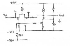
EUVL said:Quick & dirty, just to illustrate the idea.
Patrick
yup; I see now .
that's cunnin' ........... hehe - even more cunnin' than my cunnin'
edit:
in that case you don't need 1K in right half of 2SJ ;
so - there is no need for current mirror
editedit:
after third look .........
dunno it is J511 solution really simpler, just because we still need pretty nice filtered lower lower rail
later..........
at least - there are now more than just two paths for solving that ..... I see now at least 4
> in that case you don't need 1K in right half of 2SJ
I only build balanced. So I actually would need 2x J511.
> dunno it is J511 solution really simpler, just because we still need pretty nice filtered lower lower rail
The J511 has a dynamic impedance of about 300k. That is a lot of PSRR (>45dB), compared to none if you hook the 1k to -28V.
> at least - there are now more than just two paths for solving that ..... I see now at least 4
A better one would be one without any additional -ve supply.
That is now the challenge.
Patrick
- Home
- Amplifiers
- Pass Labs
- Aleph J Schematic