I just had to build another computer so I had to research quiet fans. The three I have experience with are Fractal Design, Noctua and BeQuiet. All have good, quiet bearings and I can hardly hear them up close. You can get them from NewEgg or similar. In general the 140mm move more air with less noise than smaller ones. You might want to lower the voltage a little to make them dead quiet up close. If you can just get a fan to blow some air across your heatsinks, or close to them, that might be enough.I think that I just need to move the air a bit. I found a few at coolerguys.com. This one looks interesting: Coolerguys Dual Blower Fan Component Cooler with Manual Speed Control (Lite)
They have a few others that might do also. There is another that is a pair of 120mm fans that would either blow over the top or suck air in.
I have limited options wrt placing the amp, Bob, and a fairly significant WAF to deal with.


in other words it's not a bug, it' a feature
There is a man with the right way of looking at life.
I have a pair of 2SJ74 of which one measures Idss 7.972mA and the other 8.861 (+11%).
Will they work together or should I better keep looking for a closer match?
Hi ,
I have used this chart many times, it's in post #144
http://www.diyaudio.com/forums/pass-labs/208880-f5x-euvl-approach-build-thread-15.html
Hope it helps you out
NS
Last edited:
This chart, from post #15?
http://www.diyaudio.com/forums/pass-labs/208880-f5x-euvl-approach-build-thread.html#post2947487
http://www.diyaudio.com/forums/pass-labs/208880-f5x-euvl-approach-build-thread.html#post2947487
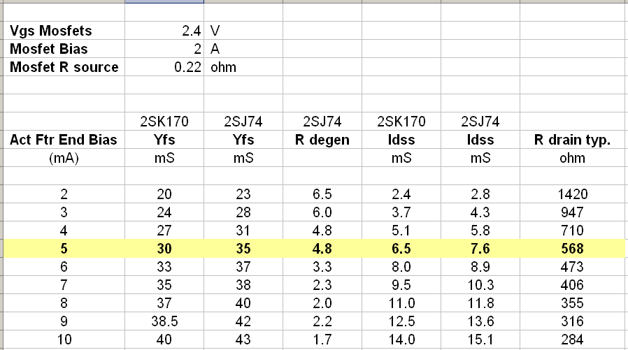
fitzfish said:Finding quads in the same range that he uses may be challenging unless you have a large number of parts to select from. In the table below Patrick lists calculated values for the degeneration resistors at various Idss combinations. This is a good place to start with selection based on the datasheets curves for the J74 and K70. Because every transistor is slightly different these numbers will not be exact. Select your parts to configure the front end bias at 5mA or higher (the yellow line and below in chart). A lower value here will dictate changing the drain resistor combination on the amplifier board. You can pre-select your parts with a Rdegen of zero ohms to see what you have, then change the 5 ohm resistor in the matching fixture to the calculated value from the chart. My quads ended up with the best match using 6.8/7.8mA Idss selected parts with 4R degeneration for the J74s.
Member h_a has transistor kits, buzzforb has matched output transistors, spencer has matched jfets, and I have full kits with all the parts (transistors and passives) to stuff the amp pcb. (PSU parts available also). http://www.diyaudio.com/forums/group-buys/241063-aleph-j-kit-parts.html
Just add a little resistance in the source, to adjust the current through the individual jfets.
Because there is a CCS on the input circuit, its relatively straightforward.
BUT, having the pot in the leg of the diff pair (R7) will make up for some or all of the imbalance if your jfets are not tightly matched.
Because there is a CCS on the input circuit, its relatively straightforward.
BUT, having the pot in the leg of the diff pair (R7) will make up for some or all of the imbalance if your jfets are not tightly matched.
Hi 6L6,
I'll give that a try and see how it does,Is it best to test with a scope and a known sine wave input to adjust the equal gain of each fet or relie on current match through the DUT? I have a few matched FETs and a whole lot of close ones and the pile of all the others,lol. just trying to get some unused ones to have a life,and the best circuit I can achieve,I am thinking If I can get them into operating range without clipping should be good enough to work. I know to adjust the pots but just wondering if the Operating range can be moved a little to better suit the getting everything to equal out ,I hope that made since,lol.
Thanks for your help!
NS
- Home
- Amplifiers
- Pass Labs
- Aleph J illustrated build guide