Hi Zen Mod,
U are right off course. I have read a lot of posts, so will try to come up with meaningful measurements.
Uncertain about the fact that the jfets are getting so hot and do not want to damage them as they are expensive... is it possible to take them out and still measure voltages?
U are right off course. I have read a lot of posts, so will try to come up with meaningful measurements.
Uncertain about the fact that the jfets are getting so hot and do not want to damage them as they are expensive... is it possible to take them out and still measure voltages?
Hmm.
I have found my mistake: when measuring/comparing, I found out that I stupidly put in a jumper on R8. It was like the game where you have two drawings and you have to look for the differences... that last one is always hard to spot.
I have put in a 1K resistor and it seems to warm up nicely.
Is there a way of quick determining if Q1a/b have passed away? If so, I should order a new pair so they arrive while i make the enclosures.
Thank you for your help, really appreciate it.
even if started with best intentions , to produce pcbs with all flexibility possible , thread result is that too many greenhorns are grinding their teeth , making every mistake possible ....
OK - leave 1K in and measure voltage across it
re-read setting procedure and , if something is wrong , come back here with full set of measurements
OK - leave 1K in and measure voltage across it
re-read setting procedure and , if something is wrong , come back here with full set of measurements
well, first impression with this aleph j was a bit clumsy
but the detail and other goodness can be feel directly
so i think, the component need to be break in for a while.
several days waiting, no changes in sound quality.
and then i try to change the volume pot,
before was alps blue velvet 10k

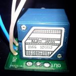
changed into this 10k 24step attenuator

very very much more improvements
finally the true sounding of aleph J can be heard clearly.
a real nice amp. no regret. i love it.
6L6, no need to apologize, was my mistake after all.
I believe all mosfets are warming up nicely and bias and offset can be set OK. Offset is wandering a little, but that's normal it seems.
I'll make a second power cable to fire both channels up, see if they warm up evenly and will measure both tomorrow.
I believe all mosfets are warming up nicely and bias and offset can be set OK. Offset is wandering a little, but that's normal it seems.
I'll make a second power cable to fire both channels up, see if they warm up evenly and will measure both tomorrow.
That sounds reassuring.
I'll do final checks tomorrow and will connect a source and speaker to see what it will do.
BTW: voltage across R8 was 8.59V.
As for C1: I plan to use a tube preamp with a capacitor in the output or maybe the B1, so I omitted C1. No problem to put an MKP in anyway, I have 2 1.0 uF WIMAs that would fit the bill.
Thanks!
I'd like to avoid a turn-on/off thump if possible. Could I switch the outputs to speaker with a DPST switch, similar to this? 1241.6821.1120000 Schurter | Mouser My thought was, just run the pos. out from both channels and switch those. Keep the speakers off for a minute or two after power on to avoid that thump, turn the switch off before power-down to avoid that thump. I have a Denon poweramp that has A/B speaker switches and I've used those to avoid the dreaded thump. Without DL'ing the service manual or opening it up, I'm just guessing that they're simple switches. I've been wrong before. Is my line of thinking wrong? Would it be bad to switch the speaker outputs? If it is OK, is it best just to switch the pos. out with a DPST switch or would I need to switch both pos. and neg. for each channel? If the latter, what type of switch would I use? (4PST? If that, links to a good example would be helpful).
if that makes you happy , why not
http://www.mouser.com/ds/2/358/typ_MSM19LA-182259.pdf
even if I would put nice speaker protection circ ,more elegant and more functional solution
http://www.mouser.com/ds/2/358/typ_MSM19LA-182259.pdf
even if I would put nice speaker protection circ ,more elegant and more functional solution
if that makes you happy , why not
http://www.mouser.com/ds/2/358/typ_MSM19LA-182259.pdf
even if I would put nice speaker protection circ ,more elegant and more functional solution
Many things make me happy. I do a lot of things that make me happy but probably aren't right.
If you have a better alternative, I'm all ears (and eyes). I do have a speaker relay board from the store but am lost in how to use it. I read about people having soft-starts and relays installed but still having thumps on turn on/off. I'm not the best at post-problem solving and like to correct things before they may happen, if possible. A bit over my head but willing to learn, and follow.
is there any related thread or maybe just part of some , regarding said spk. relay board ?
This is where I'm a bit lost. The store points to the V3 thread. 4 pages, 3 of which are straightening out which BJT to use. I don't know how relative the V2 builds/discussions are, etc. and don't want to make mistakes.
If the relay works at start-up, there should be no thump. Is it also supposed to work at shutdown as well?
I've read the V2 speaker thread and found a great SoftStart guide, but not one for the relay, unfortunately. The advice in that thread is to NOT share the main toroid but to purchase a separate 10-15VA toroid. Also, in typical DIY fashion, it seems that a portion of the posters are against the schematic, some even pointing to a product by Rod Elliott.
Now I'm left in a pickle. ZM and others don't seem to care for the softstart, without modifications, others don't really care for the speaker relays. With the relays, I'm left with two quetions: 1) Will it deal with turn-off thump, 2) Would it actually save my speakers if a large rail DC was sent? Some talk about fusing relays with large spikes, etc., so what's the point then? If it's just to keep a turn-on/off thump away, that could be done with a simple switch.
I'm not the best DIY'er. I do better when there's a proven project that works and a set of instructions. I don't do as well with the "try it and see, then tinker with components and values to get what you want." I don't mean that as an excuse, just that I know my limits.
much better to ask myriad of questions then progress , than to rush and make mistakes
regarding your spk prot. pcbs - just start the thread and ask ; ppl started so much threads for most trivial questions , not to mention repeating them again and again .......
spk protection is good ; at least for me - I'm not having welder demanding spks , so relay in my amp isn't critical as is in , say , 1KW PA monster
regarding soft start - Papa's usual solution with sole NTC is clever , while soft start relay equipped board/solution is full Monty only if equipped with NTCs instead of ceramics ........ then being in fact nothing else than Pa's NTC solution with increased resistance , bypassed with relay after initial time
regarding your spk prot. pcbs - just start the thread and ask ; ppl started so much threads for most trivial questions , not to mention repeating them again and again .......

spk protection is good ; at least for me - I'm not having welder demanding spks , so relay in my amp isn't critical as is in , say , 1KW PA monster
regarding soft start - Papa's usual solution with sole NTC is clever , while soft start relay equipped board/solution is full Monty only if equipped with NTCs instead of ceramics ........ then being in fact nothing else than Pa's NTC solution with increased resistance , bypassed with relay after initial time
much better to ask myriad of questions then progress , than to rush and make mistakes
regarding your spk prot. pcbs - just start the thread and ask ; ppl started so much threads for most trivial questions , not to mention repeating them again and again .......
spk protection is good ; at least for me - I'm not having welder demanding spks , so relay in my amp isn't critical as is in , say , 1KW PA monster
regarding soft start - Papa's usual solution with sole NTC is clever , while soft start relay equipped board/solution is full Monty only if equipped with NTCs instead of ceramics ........ then being in fact nothing else than Pa's NTC solution with increased resistance , bypassed with relay after initial time
I appreciate the feedback. Like many here I have a mountain of projects but limited funds. If I can prioritize and minimize, that's always good.
Regarding the soft-start, I'd had a conversation with 6L6 about this. He'd relayed that you felt the four 5W, 180R large resistors should be replaced with two CL-60's? Is that correct? It's possible that I have that portion wrong though.
I have zero problems asking a question that's been asked before. There is a wealth of information on this site but it's been my experience that most threads can go off-track quickly and questions about parallel projects or other things get answered, then lost in the ether.
........
Regarding the soft-start, I'd had a conversation with 6L6 about this. He'd relayed that you felt the four 5W, 180R large resistors should be replaced with two CL-60's? Is that correct? ......
3pcs of CL60 in series , even better
- Home
- Amplifiers
- Pass Labs
- Aleph J illustrated build guide