I just dusted off and upgraded the caps on my Aksa Lender today. Using SMT MELF boards and they sound superb. Without any changes to bias current settings I was driving 55ohm headphones superbly. It also drives my speaker amp well too.
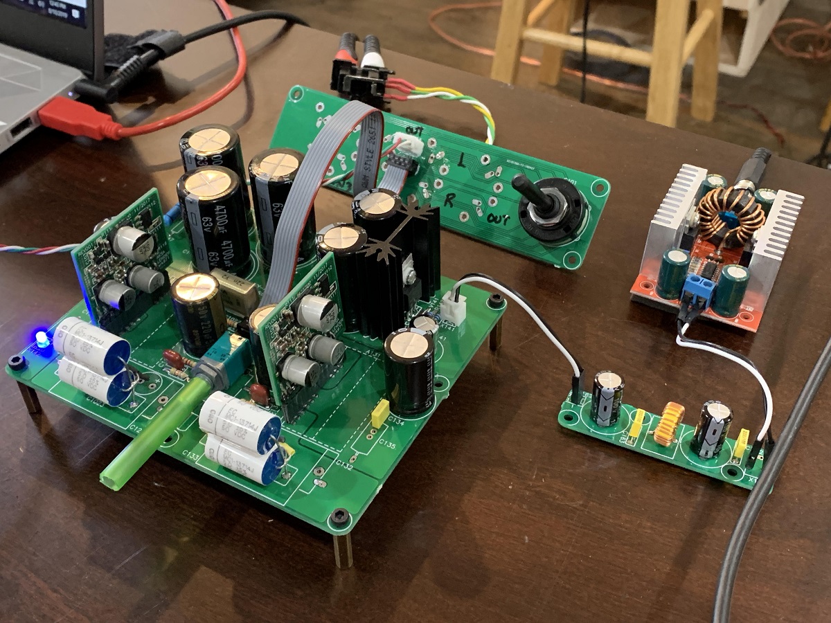
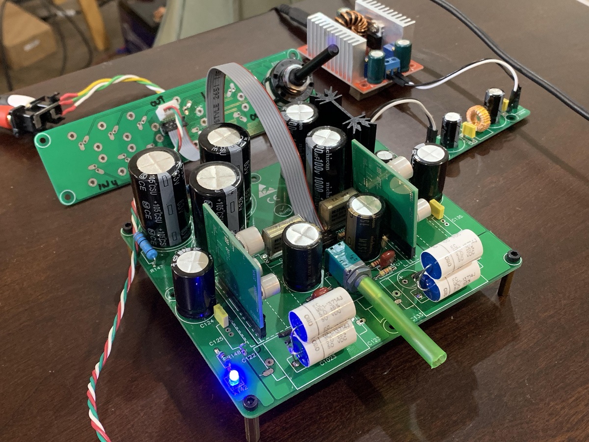
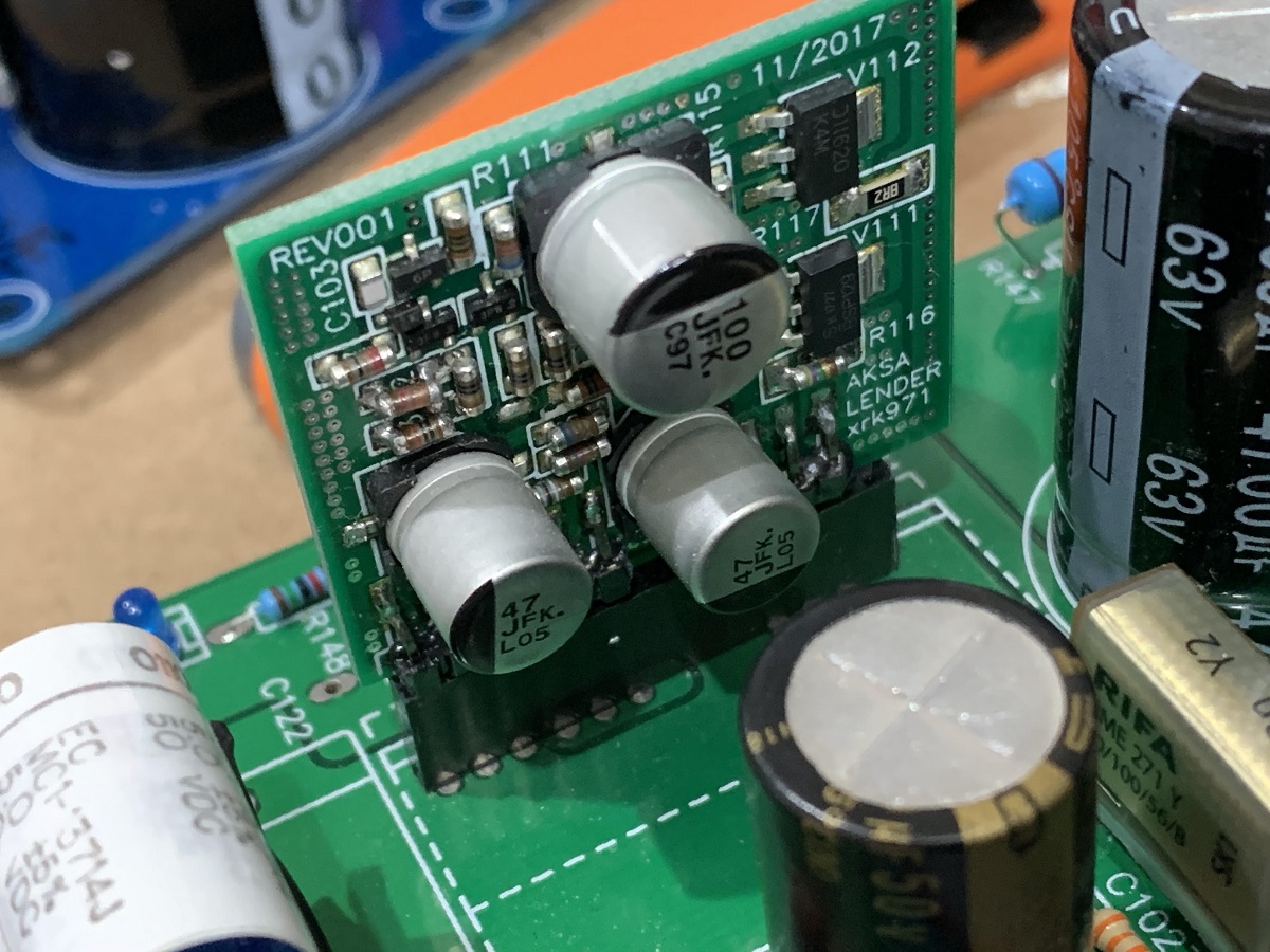
Trying out some polycarbonate film input caps and metallized paper bypass caps on the output with a 220uF 50v Muses cap. This combo sounds very very good the detail and imaging is super. Bass articulation and detail is fantastic too.
Trying out some polycarbonate film input caps and metallized paper bypass caps on the output with a 220uF 50v Muses cap. This combo sounds very very good the detail and imaging is super. Bass articulation and detail is fantastic too.
Interesting, but where can you still source polycarbonate caps? As far as I know they are being replaced with polyphenylene sulphide (PPS) caps. And I have always wondered about the usefulness of the metallized paper caps.Trying out some polycarbonate film input caps and metallized paper bypass caps on the output with a 220uF 50v Muses cap. This combo sounds very very good the detail and imaging is super. Bass articulation and detail is fantastic too.
The Polycarbonate caps were gifted to me from Vunce. I have heard that they are out of production - perhaps will be unobtainium soon? I have heard that PPS caps are supposed to be very good too. I do think that the readily available metallized paper caps sound very nice. Paper seems to have a lot of uses in audio. Speaker cones use it extensively.
Bonjour,
I have been quite impressed by all the good comments about this preamplifier and I wanted to try to build it, however I had some constraint about the assembly
First I didn't want to have plugable modules, even if I understand that it is an interesting way to test different versions. I also wanted to avoid SMD since I have a lot of leaded components and no SMD parts !
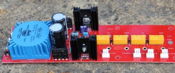
To buy PCB at a very low price from Chine, I limited the size of the board at 10 cm x 10 cm, therefore I didn't had the room to include the power supply circuitry. This is not really a problem for me because I am planning to design a PCB for a complete power supply with a small transformer like this one : 70044 TALEMA - Transformateur: moule 70044K | TME - Composants electroniques that could be used for different project with single or dual output ( I have already designed one in the past, see picture)...
I used the first version in the post 957 of XRK ( AKSA's Lender Preamp with 40Vpp Output ) and added the input and output capacitors and resistors. I did not add the pot because I didn't have a lot of space and I wanted to have the choice of different solutions
All your comments and suggestions will be greatly appreciated
Regards,
Marc
I have been quite impressed by all the good comments about this preamplifier and I wanted to try to build it, however I had some constraint about the assembly
First I didn't want to have plugable modules, even if I understand that it is an interesting way to test different versions. I also wanted to avoid SMD since I have a lot of leaded components and no SMD parts !
To buy PCB at a very low price from Chine, I limited the size of the board at 10 cm x 10 cm, therefore I didn't had the room to include the power supply circuitry. This is not really a problem for me because I am planning to design a PCB for a complete power supply with a small transformer like this one : 70044 TALEMA - Transformateur: moule 70044K | TME - Composants electroniques that could be used for different project with single or dual output ( I have already designed one in the past, see picture)...
I used the first version in the post 957 of XRK ( AKSA's Lender Preamp with 40Vpp Output ) and added the input and output capacitors and resistors. I did not add the pot because I didn't have a lot of space and I wanted to have the choice of different solutions
All your comments and suggestions will be greatly appreciated
Regards,
Marc
Attachments
... All your comments and suggestions will be greatly appreciated
Regards,
Marc
Very nice! Very nice indeed. Do you intend to share the gerbers?
Nice work Bandol83. If you don’t like SMT or removable daughterboards, you could just solder the TH board directly on. Imagine this board without the header pin edge connectors. One thing to beware of in making your own layout. A SE Class A preamp has zero PSRR. Any noise on the PSU ripple is audible as hum or hiss. That’s why the Aksa Lender mainboard has a cap Mx. Can your LM371 regulate to allow ripple down to -120dB SNR? Also, proper star ground topology and symmetry is really important to prevent ground loop noise. If you look at JPS64’s layout, the star hub is at the 8pin connector. The ground planes for left and right are separate and come together at the star hub.
Hi xrk971,
Thanks for the comments
You will find me a little exigeant may be but I don't like vertically mounted resistor too
May be this is because I lived more than 40 years in Switzerland where everything is clean and well aligned
That is the reason why I try to align components and design symmetrical PCB for stereo preamplifier or left and right channel
Regarding power star ground, I think that was very useful with old fashion point to point wiring but with PCB design the possibility to have a full board ground plane on the bottom, and even a 48 V power supply plane on top make this concept less useful, it is like if you have a virtual star ground all over the board
I have used this technology in most of my audio PCB with tubes AND transistors and never experimented noise...
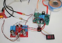
Regarding the power supply, I didn't intend to use LM317, I think you suggested that because you see them on the picture, that was just to show the low noise toroidal transformer and these regulators were used for digital power supply (5 V and 12 V)
I could make the power supply with a cap Mx, but I may also test a very low noise regulator : LT3080 https://www.analog.com/media/en/technical-documentation/data-sheets/3080fc.pdf that I have been using in high voltage power supply (see picture).
Rgds,
Marc
Thanks for the comments
You will find me a little exigeant may be but I don't like vertically mounted resistor too
May be this is because I lived more than 40 years in Switzerland where everything is clean and well aligned
That is the reason why I try to align components and design symmetrical PCB for stereo preamplifier or left and right channel
Regarding power star ground, I think that was very useful with old fashion point to point wiring but with PCB design the possibility to have a full board ground plane on the bottom, and even a 48 V power supply plane on top make this concept less useful, it is like if you have a virtual star ground all over the board
I have used this technology in most of my audio PCB with tubes AND transistors and never experimented noise...
Regarding the power supply, I didn't intend to use LM317, I think you suggested that because you see them on the picture, that was just to show the low noise toroidal transformer and these regulators were used for digital power supply (5 V and 12 V)
I could make the power supply with a cap Mx, but I may also test a very low noise regulator : LT3080 https://www.analog.com/media/en/technical-documentation/data-sheets/3080fc.pdf that I have been using in high voltage power supply (see picture).
Rgds,
Marc
Attachments

Hi Carl_Huff,
Thanks for the appreciation
I would not have any problem to send you the Gerber files, but it is not my schematic and I know that XRK is selling PCB therefor I am not sure it will be fair to offer a copy of his design with just a different PCB
Rgds,
Marc
Hi Marc,
Thank you for being considerate and asking. I am selling this in my shop and it has been a very active product that is contiunuing to sell well. I would appreciate it if folks buy these boards and use them as they are well-documented, proven to work extremely well, and will be well-supported for technical questions. Having said that, this is a public forum and the schematic is public domain. If you made your own layout, certainly, you are welcome to use it and make your own boards. As a courtesy to Aksa, JPS64, and myself, I would ask that you keep your Gerbers private.
Regarding star topology and ground plane: I have seen JPS64 use ground planes, but he still cuts the planes to isolate the various ground plane blocks and then connects them to a star hub located physically in the middle of the board. As JPS64 once told me, "You have to think like an electron!" when laying out the design for ground paths. In any event, it seems to work very well. If you want a separate ground plane and a power plane, you will need a 4 layer board.
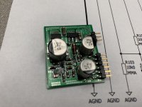
So JPS64 actually applied this principle to this preamp, back in this thread, you can see a closeup of the ground plane and how it is segmented and all paths lead to the star hub located at the 8pin I/O connector. Even the pot has two ground planes (left and right) and the split goes down the middle of the pot:
Here is the trace side with signal connections, routed for symmetry and as close to equal impedance as possible:
Hi Carl Huff,
If you would like to try Marc's PCB, perhaps he has spares he can offer you for cost of shipping and manufacturing? Have you tried making an Aksa Lender using the JPS64 designed board? It has the advantage of being a proven and supported design.
Regards,
X
Last edited:
Hi,
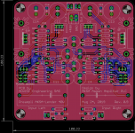
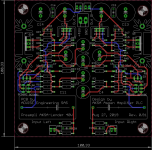
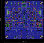
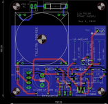
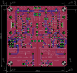
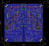
I have made some little improvement to the PCB and I think it is now ready for manufacturing. I put more tracks on the top side to have the largest ground plane on bottom side
I have added a picture of the PCB without power planes to make it more readable for those who are willing to check if there is any error
As requested by XRK I will not put Gerber on line but you can contact me by PM if you want to buy some extra PCB, this will not be a GB only few boards will be available and there will be no documentation !
Rgds,
Marc
Attachments
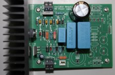
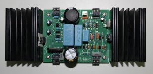
This is a low noise power supply for the preamplifier
It is a low voltage version of a tube preamplifier power supply which give me total satisfaction
It is a modern version of the "Maida" LM317 high voltage power supply adapted to the new regulator LT3080 with very low noise ( LT3080 High Voltage Floating Regulator )
I use a 10 VA toroidal transformer with 2 x 10 VAC, I think it is enough for the preamplifier ?
Rgds,
Marc
Attachments
If you are using this preamp at the design voltage of 48v and circa 25mA bias current then dissipation of main outputs is 48vx0.025Ax2=2.4W. The other stuff is another 1watt or 3.4W total. So 10VA should be fine. If you plan to run higher bias current of 50mA then 6w to 7w might be pushing it for 10VA. A 20VA will give you more headroom and less voltage sag. What voltage were you planning on using?
Thanks for the feedback
The transformer I have in stock is 2 x 18 VAC that are connected in serial therefor I am planning to use 36 * 1.4 = 50.4 VDC at the input of the bridge which will drop 2 V, about 48 V before regulation and 44 V after the LT3080
I have also an external AC/DC power supply EADP-18FB ( Amazon.com: NEW Genuine OEM CISCO DELTA EADP-18FB B 48V 0.38A Power AC Switching Adapter: Computers & Accessories ) and I can use it in front of the regulator to make some test...
I will let you know the result.
Rgds,
Marc
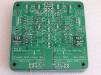
I have received the PCB today and they look nice
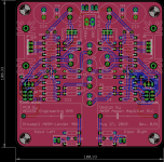
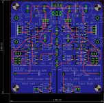
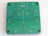
However, after sending the Gerber files to the manufacturer I found that one of the fixation hole was not aligned (top right), it is a minor problem but I corrected it and while I was doing this little modification I decided to make a new PCB layout with more space for the small heatsink... This is only for the fun of doing it since I don't intent to produce it because it is a design sold by XRK
You can have an idea of the change on the following pictures
I have two request for prototype boards, if someone is interested, please send me a PM, I will ship only single piece for 10 € plus shipment cost because of the limited availability as few boards are available
XRK if you are interested to test it, I can send you one, free of charge if you give me your post address by PM
I will let you know how it sound when it will be built...
Rgds,
Marc
Attachments
- Home
- Source & Line
- Analog Line Level
- AKSA's Lender Preamp with 40Vpp Output