It allows the Aksa Lender preamp motherboard to have the sonic character of SE Class A MOSFET follower with JFET input - same topology as the Pocket Class A (PCA) headphone amp. A very simple 2 transistor amplifier that sounds wonderful. Higher dominant second order distortion circa 0.06% THD. Kind of a sweet tube-like sound. Zero global feedback. Very quiet background. In fact, with inputs shorted - you cannot tell it is turned on.
xrk971 Pocket Class A Headamp GB
Also similar to the DCA:
xrk971 Desktop Class A (DCA) Headphone Amp
However I have added provision for using 3 types of JFETs: BF862(original), 2SK209, and 2SK170.
xrk971 Pocket Class A Headamp GB
Also similar to the DCA:
xrk971 Desktop Class A (DCA) Headphone Amp
However I have added provision for using 3 types of JFETs: BF862(original), 2SK209, and 2SK170.
Last edited:
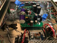
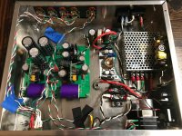
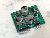
I got mine up and running about six months ago. It sounds great and has been trouble free until just recently. I usually listen to it all evening, but my wife has a bad habit of turning everything off if I'm not actively sitting and listening. The last few days, when I go to turn it back on, the Mean Well SMPS will start up in 'hiccup' protection mode. The model is RS-35-24, the data sheet states it will go into this protection mode for overload or over-voltage. Does anybody have any ideas what could be causing this or how to start investigating?
Attachments
Hi Bologna,
Disconnect the power train and start by powering up each part one by one. First, the Meanwell all by itself. Check voltage. Then add DC step up. Then the CLC. Then the Aksa Lender. Checking voltage each time. Report back what each voltage is.
The cap multiplier is needed to prevent the supplies from pulling too much current st turn on. If it is bad - the power supplies will do the self-protect thing. You might have a blown MOSFET in the cap Mx. But that’s hard to do with simply turning on/off.
There should be a circa 3v to 4v drop before and after the cap Mx if it’s working. Report those voltages.
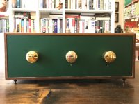
Nice build, BTW!
Good luck!
Disconnect the power train and start by powering up each part one by one. First, the Meanwell all by itself. Check voltage. Then add DC step up. Then the CLC. Then the Aksa Lender. Checking voltage each time. Report back what each voltage is.
The cap multiplier is needed to prevent the supplies from pulling too much current st turn on. If it is bad - the power supplies will do the self-protect thing. You might have a blown MOSFET in the cap Mx. But that’s hard to do with simply turning on/off.
There should be a circa 3v to 4v drop before and after the cap Mx if it’s working. Report those voltages.
Nice build, BTW!
Good luck!
Last edited:
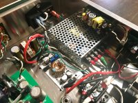
Looks like your cap Mx is not working because there is no voltage drop at CRC. Should be 4v less than 40.4. Before the cap Mx is the DC-DC (at output of CLC). After cap Mx is the CRC. You probably need to change the IRF610 in the cap Mx. Without the slow ramp of the cap Mx the meanwell sees the huge cap load of the CRC and shuts down thinking it’s a short.
It allows the Aksa Lender preamp motherboard to have the sonic character of SE Class A MOSFET follower with JFET input - same topology as the Pocket Class A (PCA) headphone amp. A very simple 2 transistor amplifier that sounds wonderful. Higher dominant second order distortion circa 0.06% THD. Kind of a sweet tube-like sound. Zero global feedback. Very quiet background. In fact, with inputs shorted - you cannot tell it is turned on.
xrk971 Pocket Class A Headamp GB
Also similar to the DCA:
xrk971 Desktop Class A (DCA) Headphone Amp
However I have added provision for using 3 types of JFETs: BF862(original), 2SK209, and 2SK170.
ah I see, Thanks man.
Sorry X, there was a typo in my last post. The voltage after the CLC (not CRC) is 40.4V. What I don't know how to measure is the CRC (or after cap MX), where exactly do I check voltage for that?
Right now, I seem to be able to turn it on and off, the LED on the SMPS flashes a couple times on start up, then seems good. However, the last few nights, when I tried turning it on after it had been off only a few minutes, it went into protection mode. It would work again after letting it sit overnight.
Thanks for all the help!
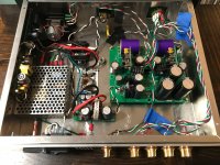
Your cap Mx is working then. Can you measure what the bias current is in the amp modules? That’s done by measuring the voltage across one of the resistors above or below the output BJT. If those show reasonable and steady numbers, the problem would then have to be the PSU or the DC-DC converter. There are two trim pots for adjustment on the DC-DC converter: one sets voltage and other sets current. If you are close to the max current setting it may do strange things.
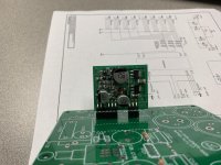
I have populated one channel preamp and I am starting on the mother board. The socket I purchased wasn't deep enough for the pins on the daughter board so they needed to be trimmed 
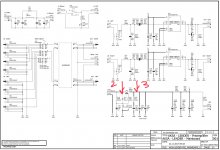
Correct me if I am wrong, but looks like R122/132 and C121/131 make a low pass filter. If that is correct than with the parts listed on the BOM the Fc would be 328Hz. Shouldn't a low pass filter on the input have an Fc of >20kHz?
Nevermind, that would 328kHz. I put in 220nF for the calculation not a 220pF.... need more coffee
Attachments
Last edited:
- Home
- Source & Line
- Analog Line Level
- AKSA's Lender Preamp with 40Vpp Output