No prob Do!
I forgot to add this link as an example:
BEL HB48-0.5-AG AC-DC Power Converter Supply 100-264VAC 24W | eBay

I forgot to add this link as an example:
BEL HB48-0.5-AG AC-DC Power Converter Supply 100-264VAC 24W | eBay
Did anyone found another source or equivalent part for the RCA connector on the selector PCB?
Looking for it as well.
Kind regards,
Drew
ok found some on AliExpress. They're 90 degrees BUT here's how to retrofit them, I think... I'll order some, there's many resellers. The link below is just an exemple...
20Pcs High quality Copper Gold Plated RCA Terminal Female Jack Panel Mout Chassis Audio PCB Socket Connector-in Plug & Connectors from Consumer Electronics on AliExpress
So, looking at the picture below, pull the pins (arrow), there's two of them, and insert them in the holes (yellow circles). Then straighten the pins (blue circle). The connector should now properly fit the PCB!

Let me know what you think?
Do
20Pcs High quality Copper Gold Plated RCA Terminal Female Jack Panel Mout Chassis Audio PCB Socket Connector-in Plug & Connectors from Consumer Electronics on AliExpress
So, looking at the picture below, pull the pins (arrow), there's two of them, and insert them in the holes (yellow circles). Then straighten the pins (blue circle). The connector should now properly fit the PCB!
Let me know what you think?
Do
Exactly Do.
The thick pins can be pulled and installed for either straight or 90° mounting. They do not have any electrical contact to ground, strictly for mount purposes.
I preferred these though:
MANLEY RCA Gold-plated & Teflon phono jack Brand NEW! | eBay
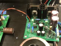
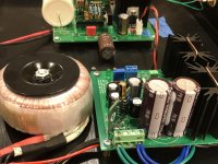
This preamp is the Tweakers Dream! I’ve been playing around with another PSU setup.
AMB Sigma11 with Prasi’s LT4320 SMT Ideal Bridge retrofitted on the Sigma11 board. Freshly fired up, I’ll get some listening hours in to see what is different.
The thick pins can be pulled and installed for either straight or 90° mounting. They do not have any electrical contact to ground, strictly for mount purposes.
I preferred these though:
MANLEY RCA Gold-plated & Teflon phono jack Brand NEW! | eBay
This preamp is the Tweakers Dream! I’ve been playing around with another PSU setup.
AMB Sigma11 with Prasi’s LT4320 SMT Ideal Bridge retrofitted on the Sigma11 board. Freshly fired up, I’ll get some listening hours in to see what is different.
Attachments
Are you limited to 36V with the Sigma11? I'm thinking... What if you use a Sigma22 @ 25V but don't use the gnd as reference, you should get 50V. I really like the Sigma series and use them in many projects. I like the retrofit of ideal bridge! I might end up doing this since I've got quite a few of those PCBs. The only thing is that darn LT4320, so expensive!
Do
Do
I don’t know what the AMB puts out, but looks like it’s dual rail (isolated from gnd) and Vunce has the -ve going to ground on the Aksa Lender and positive to +ve input. You need about 51v to 52v at the input. There is an on-board cap multiplier that drops 3.5v to 4v. You want about 48.2v (ideally) at the Aksa Lender daughterboard V+ input for the best performance in harmonic profile.
I can also confirm that swapping out a diode bridge rectifier for an LT4320 based one makes a very noticeable difference in amplifier sound quality. The transparency, soundstage, imaging, and noise floor all improve. It’s a no-brainer for me now. I agree the price of that LT4320 and MOSFETs isn’t cheap. But for high current applications, not using 8 TO220 MUR diodes and their required heatsinks, spacers, washers, etc - the costs are even. The complexity is way less for huge performance gain in voltage headroom and no heat.
I can also confirm that swapping out a diode bridge rectifier for an LT4320 based one makes a very noticeable difference in amplifier sound quality. The transparency, soundstage, imaging, and noise floor all improve. It’s a no-brainer for me now. I agree the price of that LT4320 and MOSFETs isn’t cheap. But for high current applications, not using 8 TO220 MUR diodes and their required heatsinks, spacers, washers, etc - the costs are even. The complexity is way less for huge performance gain in voltage headroom and no heat.
Last edited:
Hi X,
I received the PCBs, thanks very much for everything!")
I've just found a PoE injector at the office that supplies 52Vdc @ 600mA. That should be good to test and get things going.
Just wanted to know if there are any transistors that require matching?
And last question, for the carbon resistor, I've got three brands in mind but not sure which one would be best... Or it is just a matter of personal taste...
Takman Carbon Film
Takman Carbon Film REX Series 0.25 Watt Resistors
Arcol Carbon Comp
Arcol 0.25 Watt Resistors
Amtrans AMRT Carbon Film
Amtrans AMRT Carbon Film 0.25 Watt Resistors
Then I can start my build in peace! LOL
Do
I received the PCBs, thanks very much for everything!
I've just found a PoE injector at the office that supplies 52Vdc @ 600mA. That should be good to test and get things going.
Just wanted to know if there are any transistors that require matching?
And last question, for the carbon resistor, I've got three brands in mind but not sure which one would be best... Or it is just a matter of personal taste...
Takman Carbon Film
Takman Carbon Film REX Series 0.25 Watt Resistors
Arcol Carbon Comp
Arcol 0.25 Watt Resistors
Amtrans AMRT Carbon Film
Amtrans AMRT Carbon Film 0.25 Watt Resistors
Then I can start my build in peace! LOL
Do
And last question, for the carbon resistor, I've got three brands in mind but not sure which one would be best... Or it is just a matter of personal taste...
My vote goes to Vishay metal foil, check out my measurements at https://www.diyaudio.com/forums/gro...der-preamp-40vpp-ouput-gb-41.html#post5576044. Like Vunce said, this one is a tweaker's dream!
Greg
Anyone can let me know if there are transistors to match on the smd boards? I mean TH board should be similar as well.
X, Anyone?
This lowered the noise floor but did you check the harmonic profile? Is it still similar? Just curious, not crucial.
From the FFT, you can see the harmonics moved from increasing 2nd -> 3rd with a bit of 5th, to decreasing 2nd -> 3rd and everything else below the noise floor.
Anyone can let me know if there are transistors to match on the smd boards? I mean TH board should be similar as well.
I don't believe I matched any transistors in my build, but it's been a while so might want to get a confirmation

Nice Do!
I might have to try the SMT boards
Thanks!
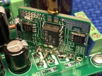
That diode on the upper left corner is 1mm * 2mm approximately! I had to zoom on it with my phone to find the cathode!
All the best!
Do
From the FFT, you can see the harmonics moved from increasing 2nd -> 3rd with a bit of 5th, to decreasing 2nd -> 3rd and everything else below the noise floor.
I don't believe I matched any transistors in my build, but it's been a while so might want to get a confirmation
If you match the Hfe of the LTP's it will be more stable over a temperature range. On the Melbourne, it is more important to match if you are running DC coupled output. On this preamp, as it is cap coupled, DC offset drift doesn't matter much.
- Home
- Source & Line
- Analog Line Level
- AKSA's Lender Preamp with 40Vpp Output