Hi X,
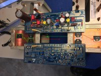
I positioned both boards to use two CPU coolers but the MOSFET’s are not centered on the copper and very close (not touching each other) together. Do you think this scenario would be acceptable?
That’s mighty close and it’s not centered on cpu cooler. I would rotate CPU cooler 90deg and center them and make more room so they don’t touch. That would be bad as the tabs are live. Funny your MOSFETs have exposed tabs. Must be Fairchild? You will need to drill custom holes for mounting the PCB rather than use existing bosses. But it’s not that hard in the soft aluminum frame of the CPU cooler.
Earthing Your Hi-Fi - Tricks and Techniques
Earthing (Grounding) Your Hi-Fi - Tricks and Techniques


That’s what I did except used two discrete MUR diodes, a 22R 2W resistor, and 1uF film.
Hi X,
I positioned both boards to use two CPU coolers but the MOSFET’s are not centered on the copper and very close (not touching each other) together. Do you think this scenario would be acceptable?
I would keep the idea, only I would move the two heatsink closer to each other.
You can drill new holes, just use some lubrication when you drill, I first drill a pilot hole with a thinner drill bit and after go with the size I need. You do not need to use the already existing holes because that would limit the layout very badly.
You can also slide the two PC boards so the mosfets do not touch each other.
I hope you can understan the idea I try to explain.
")
Attachments
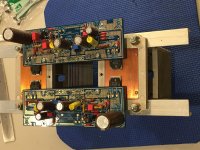
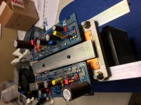
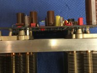
After I thought about the layout and the good input from all of you, I did change the position of the cpu coolers to get the MOSFETs closer to the center and not so close together. I drilled new holes and used 10mm brass stand-offs to mount the ALPHA boards. I do have to cut off the original cpu cooler bosses that are under the boards because they almost touch the soldered components.
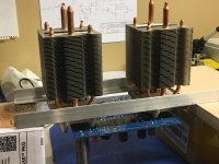
I used old transistors to mock up the layout, the new IRFP devices do not have metal tabs sticking out. I used 1” wide aluminum flat bar for the clamp to hold the MOSFETS tight to to coolers. I left extra length of angled aluminum on both sides for mounting purposes and in case I need to attach a fan.
This ‘module’ will be mounted with the coolers on topside and ALPHA boards upside down.
Attachments
Forced convection is usually used with these type of coolers, and they typically also have a much larger contact surface with the part they're cooling, so i would be inclined to think the same. Large 120 or 140mm fans at low speeds can be nearly inaudible (at least when a little music is playing), so that might be an option.
I also find that a 100R 1W resistor between 12vdc and fan motor of regular brushless dc fan slows it down to almost inaudible and cooling is still sufficient (that’s what I use now). Of course, you run the risk of fan stall, etc. hence use at own risk. But with JPs64’s new 52W design I believe a temperature monitor and auto shutoff feature may be incorporated since it relies so much on the fans, which are integral to the design for a compact and low cost heatsink that can dissipate 200w+.
Hi X,
standby until thursday but I confirm that each BB board including two independant monitored FAN supplies (TC665 with FAULT output + to mosfet wired 100k NTC).
The I2C interface going to common (stereo) µC + OLED + 12VDC supply board (PCB part of main board but needs to be cutoff and placed on the front of the enclosure) who manages main power ON/OFF (would be nice to have a booster with shutdown capability? Thinking about LTC7812/13!).
I´ve to order 3D printed PCB mockup to check mechanical assembling (50€!).
JP
JPS64,
That sounds great. Thanks for making all the nice features possible. I was thinking if one simply has a relay activated by the temperature monitor, if it applied GND to the gate of the capacitance multiplier, would that cut the power? We could also get SSR for the PSU lines? Or just get a big power relay capable of mains or
That sounds great. Thanks for making all the nice features possible. I was thinking if one simply has a relay activated by the temperature monitor, if it applied GND to the gate of the capacitance multiplier, would that cut the power? We could also get SSR for the PSU lines? Or just get a big power relay capable of mains or
I'm listening to the Alpha 20 with a new mocke-up 93dB sensitive XKi speaker using Beta 8cx and a 1in dome tweeter with passive 1st order crossover. Wow, the music really comes alive with a sensitive speaker. The aluminum dome tweeter also give some vert nice highs. If you have sensitive speakers, try them with the Alpha 20.
- Home
- Amplifiers
- Solid State
- Aksa Lender P-MOS Hybrid Aleph (ALPHA) Amplifier