Nothing but the best for AKSA/X/JP projects, lol!
I mocked up the SMPS—>DC booster—>Allo Cap Mx combo to an LM4780 chip amp to see if I was getting any hum/weird noises. Nothing, nice and quiet. I know it’s a totally different amp than the ALPHA, but wanted to make sure I wasn’t pushing the boulder uphill already")
That’s great news. I wonder if the Allo cap Mx is quieter as it is multistage BJT design with low dropout. Excellent - I think you will be successful and if so, it may be the Allo cap Mx that is filtering the noise nicely.
So I predict first sound in 3 hrs if you get the heat sinking all done?
In REW there is output level with generator. Set it to -5dB and make sure master volume is set to 1.0. Use DMM to set voltage on AC. That’s close to Vrms for sine wave.
In RTA settings use spectrum mode and choose between 16k and 32k and Blackman Harris window. Play with it. Also set gain of the input preamp to barely above level needed to make signal light glow on ring indicator of Focusrite. If orange or red it’s clipping.
In RTA settings use spectrum mode and choose between 16k and 32k and Blackman Harris window. Play with it. Also set gain of the input preamp to barely above level needed to make signal light glow on ring indicator of Focusrite. If orange or red it’s clipping.
Last edited:
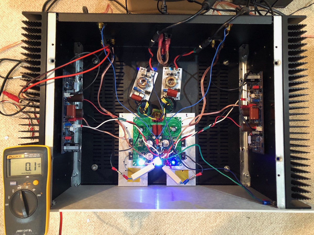
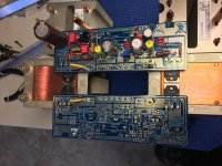
I tried Hugh's suggestions to put a 10R in between the cap mx and amp PCB on the ground wire, and add back-back diodes (with 22R in parallel and 1uF 630v in parallel) between the star ground and the chassis ground. I also grounded the chassis to earth ground. All this got the noise (with no signal input) down to 0.1mV on the Fluke 101. So the belts-and-suspenders approach here worked. Here is photo of setup (I am using power resistors, but not sure you need to?).
Setup with the 10R between cap mx and amp PCB:
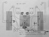
Here is schematic of above psu:

Setup with the 10R between cap mx and amp PCB:
Here is schematic of above psu:
Attachments
Last edited:
Prototyping upcoming enclosure for Alpha and second one for something else. Don't know about looks of it, but they are quite compact. I'm not so sure about remote PSU, don't feel like looking for extra trouble for now. Might rise case with little legs and add lower section for transformer if everything is not going to fit inside. I ordered Toroidys 500va 2x20v shielded trafo, since toroid will be quite close to everything. Hoping that shielding helps with that. It will take 14 days to manufacture got another trafo also for Salas DCB1.
Edit; they will get some aluminium sheets all over it, that's the last phase when everything else is working.
got another trafo also for Salas DCB1.Edit; they will get some aluminium sheets all over it, that's the last phase when everything else is working.
Attachments
Last edited:
Nice lean-to heatsink. That thing is huge! Cool idea to make it with heat sink as a roof.
Thanks, they really are quite huge! I made it this way so it's easier to make since I lack tools and space where to build. Heatsink works as roof and front plate so now I have to take care only clean side- and rear plates. Bottom will probably be 3mm aluminium so I can use it as a heatsink for CapMX.
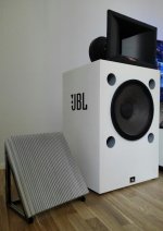
For size reference, that bass/midbass cone is 15"
Last edited:
Thanks, they really are quite huge! I made it this way so it's easier to make since I lack tools and space where to build. Heatsink works as roof and front plate so now I have to take care only clean side- and rear plates. Bottom will probably be 3mm aluminium so I can use it as a heatsink for CapMX.
For size reference, that bass/midbass cone is 15"
Juntuin,
With reference to the image you posted, for a second the wooden floor in the thumbnail image looked like a table top to me, and on top of that I thought placed was a nice desktop speaker with a bright white cabinet...
I think those four ports looked like small holes for attaching the speaker grill, and gave me the impression of smallish speaker...
Last edited:
Juntuin,
With reference to the image you posted, for a second the wooden floor in the thumbnail image looked like a table top to me, and on top of that I thought placed was a nice desktop speaker with a bright white cabinet...
I guess they would do really nice as desktop monitors
gotta get bigger desk though!So this is what I came up with....
3/4”x3/4” Aluminium angle stock will run parallel and attach the two CPU coolers above the mounting bosses to create a rigid frame. Below(copper plate side) the ALPHA board will attach using only two of the four mounting holes.
3/4” Aluminium flat stock spanning both coolers will be used to clamp the MosFets to the copper surface as close to center as possible. Two of these ‘modules’ will be made. At this point I could make a pair of mono blocks or join them together into a single chassis. I have to figure out what type of power supply I will settle on. I’m going to try the smps route first.
This is awesome Vunce, good work!
I'm likely going to do some similar mounting, still working that out.
I tried Hugh's suggestions to put a 10R in between the cap mx and amp PCB on the ground wire, and add back-back diodes (with 22R in parallel and 1uF 630v in parallel) between the star ground and the chassis ground. I also grounded the chassis to earth ground...
Earthing Your Hi-Fi - Tricks and Techniques
Earthing (Grounding) Your Hi-Fi - Tricks and Techniques


Last edited:
Hi
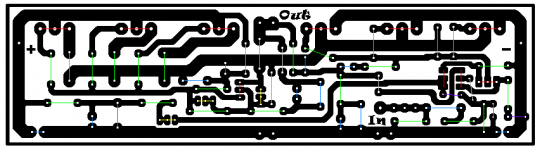
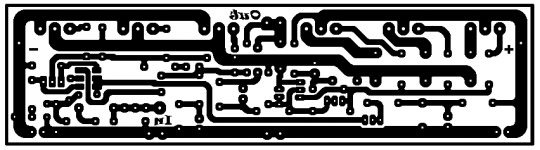
I decided I post the BigBoy layout since I worked so much on it. It is not tested but I do have several years experience doing these type of layouts. These with the 3 pair power mosfets.
I used colored code
Green Resistors
Blue Capacitors
Red Semiconductors
Grey Jumper
Yellow Trimmers
Purple Diodes
The layout was made to the DMM5401 LTP semis For BC847C I used BC550C so please take care of the pinouts if is different! Very likely is the same.
These were made to those who have some giant heatsink for the project
Is not a professional layout but can be used. I will use these if I build the BigBoy. Maybe the 20W version will satisfy my needs.
The size you aim 63x237mm from frame to frame
I decided I post the BigBoy layout since I worked so much on it. It is not tested but I do have several years experience doing these type of layouts. These with the 3 pair power mosfets.
I used colored code
Green Resistors
Blue Capacitors
Red Semiconductors
Grey Jumper
Yellow Trimmers
Purple Diodes
The layout was made to the DMM5401 LTP semis For BC847C I used BC550C so please take care of the pinouts if is different! Very likely is the same.
These were made to those who have some giant heatsink for the project
Is not a professional layout but can be used.
I will use these if I build the BigBoy. Maybe the 20W version will satisfy my needs. The size you aim 63x237mm from frame to frame
Attachments
- Home
- Amplifiers
- Solid State
- Aksa Lender P-MOS Hybrid Aleph (ALPHA) Amplifier