Spider will always have a resonance, question is can we get it to where you don't notice it. The spider is basically a weaved doped cloth glued to the outside of the coil and to the inside of the basket making like a bridge. At some certain frequency it will resonate and then the harmonics of that will sometimes show up as well. First place to look is the impedance curve for the telltale bump, then look to the frequency graph to see if there is a corresponding bump and/or dip.
Spider will always have a resonance, question is can we get it to where you don't notice it. The spider is basically a weaved doped cloth glued to the outside of the coil and to the inside of the basket making like a bridge. At some certain frequency it will resonate and then the harmonics of that will sometimes show up as well. First place to look is the impedance curve for the telltale bump, then look to the frequency graph to see if there is a corresponding bump and/or dip.
Thank you for your answer Mr. McKinney.
I know some attempts of using 3 S shaped metal, carbon or fibreglass reinforced ply pieces glued to a ring on one side (and the ring glued to the cone); the other side of the S shaped pieces was clamped to the basket with screws. What do you think of this design, is it able to limit resonances?
SunRa said:
Thank you for your answer Mr. McKinney.
I know some attempts of using 3 S shaped metal, carbon or fibreglass reinforced ply pieces glued to a ring on one side (and the ring glued to the cone); the other side of the S shaped pieces was clamped to the basket with screws. What do you think of this design, is it able to limit resonances?
Thats how spiders were made 80 years ago. I never tried them in current designs, they don't allow much xmax I would think.
SunRa said:
Thank you for your answer Mr. McKinney.
I know some attempts of using 3 S shaped metal, carbon or fibreglass reinforced ply pieces glued to a ring on one side (and the ring glued to the cone); the other side of the S shaped pieces was clamped to the basket with screws. What do you think of this design, is it able to limit resonances?
Just to add to this a little, way in the past, 50yrs ago or so, the technology for cloth material used in spiders was nowhere near what it has been more recently. Spiders were given their name because of the way they used to be made with different pieces of coiled material. They would stamp out the shape from a sheet of material which could then have some flex to it. The more coiled, the farther it could go in and out. The higher the Xmax though, the harder it was to work with and materials becoming brittle over time were a hard issue to deal with. I had an old hartley 24" woofer here that had been redone once. It had a hand made replacement "spider" cut by hand from a sheet of teflon. Seemed to work well, but it only had about 2mm of travel. Copper could work, but alone isn't flexible enough and oxidizes over time. Beryllium copper can be quite flexible and hold up over time well. You can also then use the strips, or coils as they would be, as the lead wires.
Anyway, the problem with these type of spiders, along with the fatigue issue over time is typically that they have one major resonance point. It's basically a metal spring, and that resonance is very hard to damp. Take a mass on a spring and get it moving. Now spray any kind of damping material you want on that spring and it's not going to change much. The biggest issue though is that the way the coils need to be made, they don't have a lot of stability to keep the coil from moving side to side, especially over high excursion. The spider would uncoil almost like a Slinky.
I see 2 ways that things can improve greatly in spiders in the future and have done some research into both. One is to use non-woven cloth instead of the traditional woven fabric for spiders. This is much more linear around the circumference of the spider than a woven material. Some non-woven materials have very good elongation properties, and do not fatigue over time nearly as much as woven cloths. We have one vendor who has done a lot of work with non-wovens but they aren't ready yet. The other option is to injection mold a spider from some material like santoprene which is well damped and will be consistent over long term use. This however takes a lot of FEA time and lots and lots of money to research.
In the end though, if you can't attribute any bumps in the impedance curve and corresponding bumps in the response curve to the spider, it's likely not worth the tremendous effort to improve something you can't measure or hear.
John
Just to add to this a little, way in the past, 50yrs ago or so, the technology for cloth material....
Thank you for the in-depth explanation!
Haven't had time to read the full thread yet so I hope this hasn't already been mentioned. If left as a dipole speaker with the increase in efficiency or sensitivity then this would appear to fall right in with Lynn Olsens original idea when starting out that mammoth thread. The 10 is a bit smaller than he envisaged but may well bring the cost of such a design more inline with what a lot of people could afford. I was looking at some Celestion Pro drivers for this purpose.
Maybe that big Pyle 21" that magnetar uses supporting this at the bottem and a waveguide and some form of supertweeter above it?
jamikl
Maybe that big Pyle 21" that magnetar uses supporting this at the bottem and a waveguide and some form of supertweeter above it?
jamikl
winslow said:What is the physical depth on the 10? Might be perfect for us car guys who love big midbasses provided it isn't too deep.
The depth on the 10" is about 6". We have had some interest in that, but it is a little too deep for most. We can take 1" off the depth of the TD10M at the sacrifice of about 1dB efficiency. This puts the 10M in the range of 93-93.5dB 1w with a slightly higher Q than before. For most midbass applications this works quite well yet.
John
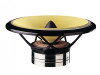
The Seas Exotic 8" full range incorporates many of the design ideas discussed in this thread, including an more open weave spider.
* underhung motor
* foam rubber surround
* light weight paper cone
* copper on pole piece
* more open weave spider
* medium Qts usable for dipole
http://www.seas.no/index.php?option=com_content&task=view&id=193&Itemid=189
"The Exotic F8 is a full range 8-inch driver designed for smooth, wide frequency response, high sensitivity, and low distortion.
The special paper cone is embedded with papyrus fibers to optimize stiffness and damping. An optimally matched whizzer cone extends high frequency response beyond 10kHz.
A special foam rubber surround reduces mass by 40% compared with conventional rubber surrounds, resulting in higher sensitivity and excellent damping properties.
A totally new and proprietary spider design dramatically improves the performance of this critical suspension part. By combining an extremely open weave with a new resin formulation, all noises normally created by the friction of the threads rubbing together are virtually eliminated. Additionally, the open weave is highly acoustically transparent, minimizing the reflections and resonances associated with conventional spider designs.
A high temperature copper voice coil is wound on a rigid, non-conductive glass fibre former.
The magnet system uses an Alnico V ring magnet for high sensitivity, excellent stability, and low distortion. A copper cap on the pole piece, combined with an under hung voice coil reduces non-linear distortion to a minimum.
New H2 lead-out wires eliminate noise due to roping and resonances."
Attachments
jamikl said:Haven't had time to read the full thread yet so I hope this hasn't already been mentioned. If left as a dipole speaker with the increase in efficiency or sensitivity then this would appear to fall right in with Lynn Olsens original idea when starting out that mammoth thread. The 10 is a bit smaller than he envisaged but may well bring the cost of such a design more inline with what a lot of people could afford. I was looking at some Celestion Pro drivers for this purpose.
Maybe that big Pyle 21" that magnetar uses supporting this at the bottem and a waveguide and some form of supertweeter above it?
jamikl
The 15" parameters are posted a few posts up above. A 12" or 10" are easily possible, however the 15" is by far the most cost effective in terms of efficiency and output per dollar.
Regarding the Pyle, I haven't taken one apart, so I can't speak for this particular driver. Without knowing how this driver is built, it is difficult to get even an idea on what it can do. They also don't give a 1w/1m number, they spec "SPL" which could mean just about anything. I would honestly be surprised if it had more than 3-4mm overhang. Also, every pyle driver I have taken apart was a typical low cost driver. No extended pole, so inductance will change greatly with excursion and as a result very high distortion. The 4" coil means inductance is already quite high. For a low cost system it could be fine, but I wouldn't expect it to be a viable option for any hi-end system.
John
LineSource said:The Seas Exotic 8" full range incorporates many of the design ideas discussed in this thread, including an more open weave spider.
Yes, this is something similar to what we are targeting in our Alnico motor drivers that will be in development over the next 6-12mos. We will be looking at more efficiency though as this driver is only 92dB 1w/1m so I wouldn't call it extremely high efficiency. You also see a big bump in the impedance curve at 700hz indicating somethings is going on there. It is more noticeably in the 8ohm version than the 4ohm.
http://www.madisound.com/catalog/product_info.php?manufacturers_id=177&products_id=8320
The other comparable driver I can think of is the Davis Acoustics 8" Alnico driver, which is no longer available. You can still see the page here:
http://www.partsexpress.com/pe/pshowdetl.cfm?&PartNumber=297-574&DID=7
If you click where the image should be, it does still come up. When you get into Alnico these days you need to have deep pockets.
")
John
Mark Seaton said:While an underhung motor is a good example where more B is often useful or desired, be cautious in blindly chasing motor strength in the name of efficiency.
Hi Mark,
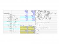
The golden ears talk about the need for very low Mms in a midrange to minimize stored energy and to keep up with the "tone" of compression drivers and ribbon tweeters. Very, very Low Mms is why Lynn Olson is looking at a compression+horn midrange over a standard speaker. Low Mms plus linear flux is what justifies the high cost of an underhung motor. Several 10" midranges have Mms between 20-25 grams, and some 12" are close to this. The underhung Seas Exotic 8" has Mms=10g and dipole like Qts=0.44 over wide bandwidth thanks to a large AlNiCo magnet.
If my numbers are correct....Even for dipole optimized midrange speakers with a Qts ~0.5 and modest BL requirements, a higher magnetic gap flux in an underhung motor allows a shorter and lighter voice coil. This can reduce weight for improved tone and efficiency, as well as increase the Xmax for a given motor pole steel length. In the 10" and 12" example data, a BL ~ 10 requires ~40 meters in a 0.25 Tesla gap flux from a 0.85" thick Ceramic_5 magnet, and 20m in a 0.5 Tesla gap flux from a 0.25" thick NdFeB magnet. For 20m of wire, a modest power midrange can use AWG 30 copper with NdFeB with a wire weight of 4.4 grams on a 4 layer coil with height of 0.32". NdFeB allows lower Mms which the golden ears demand.
Attachments
Don't have much time to respond to the above right now, but here is an old paper Nick wrote called Bl/Mms = Nonsense:
http://web.archive.org/web/20020204092008/www.lambdacoustics.com/library/whitepapers/bl_mms.htm
It explains the common myth of an "acceleration factor" in drivers based on Bl and Mms alone and what the real acceleration factor is which takes into account current.
Now, if you take 2 versions of the same driver, same motor, same coil, etc but different physical mass you can do some comparisons. We do this with the IB15 for example. With no mass added, the IB15 has about 140 grams and Fs of 24hz or so. When it is massed it has 220grams it has 16Hz Fs. Now if you normalize the levels and do an impulse response with a full range signal, you will see a longer more drawn out impulse with the heavier driver. This is what leads people to think that it is slower, has more stored energy, etc. In reality that isn't the case. Because of more mass, it has lower resonance and plays lower frequencies at higher level than the lighter driver. The lower frequencies obviously will have a longer impulse.
Now if you take the 2 drivers, normalize response to the same level and take an impulse response of a tone at say 100hz, 500hz, 1KHz, etc what you'll see is they look virtually identical. You see no more "stored energy" in the heavier mass driver. Now take 2 drivers with the same mass, but with greatly different inductance and you will see things are drastically different.
The reason people often think heavier drivers sound slower, have more stored energy, etc is simply an issue of inductance. Most heavier drivers are heavier because they have more wire in the coil, more inductance, and as a result have more limited bandwidth.
John
Picture of B&W 6.5" underhung motor midrange. You can find these for $140-$160 on eBay. The cone is woven Kevlar that goes all the way to the surround edge. My textbooks claim that woven kevlar can mix both high strength weave patterns with high dampening weave patterns to create exceptional speaker cones. B&W website has laser interferometer pictures of the kevlar cone break-up. There are a couple AES papers using laser interferometer cone measurements which cover minimal optimal cone mass vs. break-up modes vs. distortion.
The three chrome rings in the motor are:
1) thick steel top pole piece
2) thin NdFeB center magnet
3) thick steel bottom pole piece
The three chrome rings in the motor are:
1) thick steel top pole piece
2) thin NdFeB center magnet
3) thick steel bottom pole piece
Attachments
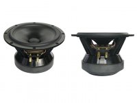
tinitus said:Hi Linesource, why do post the same text twice with 2 clearly different drivers
Hi tinitus,
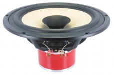
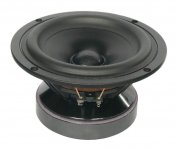
The two pictures are supposenly of the same Tang Band W8-1722, 8" midbass. One is from a European sales site, and the second from the TB home page. I think the second photo with 8 mounting holes is the real W8-1722 and the first photo with 4 mounting holes is really the 6.5" W6-1721 - mislabeled. Thanks for point this out.
I posted the Tang Band as an example of a Ceramic underhung motor for discussion.
I posted the B&W as an example of a NdFeB underhung motor and woven Kevlar cone for discussion.
The Lambda underhung motor should be pretty good, even with a 0.85" thick Ceramic magnet. The B&W motor shows some value in using a thin slice of NdFeB. I'm hoping a clever cone profile with Mms < 25 grams will get tested as one Lambda midbass option by Nick and John.
- Status
- This old topic is closed. If you want to reopen this topic, contact a moderator using the "Report Post" button.
- Home
- Loudspeakers
- Multi-Way
- AE Lambda Midbass 10 Project?