agent.5 said:
What would you want a 10db rising pattern?
It's the classic response of a driver meant for horn loading.
LineSource said:Commercial customers might also demand the 120 db to meet marketing demands.
Increasing the efficiency will reduce continuous power requirements.
I snipped a bit but basically this driver would be designed more for home/studio use. Commercial customers would have other choices from our catalog that would better suit their needs. Also this driver will be available in the current ceramic, or the upcoming Alnico or Field coil motors. We are serious in that most all of our product line will have the other motor options once they are released.
agent.5 said:probably just a few watts, as most will probably use a SET amp.
The coil will handle quite a bit as it will have all the heatsinking of the standard TD motor. I don't see a problem with even 100W for this one. Now 1KW would be another story.
swak said:I am happy to see more of us are thinking about a similar setup and that AE speakers can come up with great drivers.
Nick:
What would the approx. price increase for a field coil motor be?
John
AE speakers could offer a kit or a completed design for DIYers that wouldn't like to mess with all the design complications or don't have the technical background. I think that would certainly help selling the drivers. An 18sound XT120 horn with a CD could cover the range above the two (midbass, bass) AE drivers, with the option of a supertweeter for the range above 12K.
PS: I would like to add that it could be very interesting for some if there would be drivers designed specifically for current drive amplifiers. Thorsten (Kuei) gave some points on this forum on needed motor/driver properties and advantages of current driven speakers versus traditional voltage drive, he even sketched a system with Seas drivers.
I don't know what the field coil will cost, a lot will depend on the massive coil of wire needed and the pricing of copper when we go to production. Figure $100 to $200 extra over a regular TD I would imagine.
Design kits are on the stove as well, I talk with John most every day on this part especially with respect to getting mids and tweeters sorted out that can keep up.
What would be different in a driver designed for current drive?
tinitus said:67hz Fs, 100db, double 6ohm voicecoil, stiff surround, dipole, compression driver, waveguide ... now I am so confused I dont know what to say
That is what happens when a couple of driver engineer's can hand build whatever they can dream up. Our design is modular and based on a couple motors and the same baskets, we can mix and match multiple parts to suit the target spec. We just need to know what specs to shoot for
Question is whether they would pay the exstra dollars to get a quality driver, as many high Qts drivers come really cheap
if not your customers could very well be the hard core guys that use expencive high sensitive FR drivers, totally different ballgame ... here there may be a relatively good market fore a 15" with field coil
So it boils down to a cheapish 12" and an expencive 15"
if not your customers could very well be the hard core guys that use expencive high sensitive FR drivers, totally different ballgame ... here there may be a relatively good market fore a 15" with field coil
So it boils down to a cheapish 12" and an expencive 15"
John_E_Janowitz said:... in your model are you assuming the same size ndFeB+37 as the ceramic 5? If so, this is an extremely expensive piece of neo to start with. There are 2, maybe 3 magnetizers in all of the US that can magnetize a piece of neo this large.
John
John,
In my 2D model, a 0.85" thick (what I measured on my speaker) Ceramic magnet generated 0.18 T in the center of the gap, and a 0.25" thick NdFeB_37 ring generated 0.37 T in the center of the gap. Have you measured the gap flux in a TD15 dipole?
From product pictures, some speaker manufactures use full NdFeB rings, while other use arcs and multiple small circular disks.
For the highest efficiency underhung midrange motor, NdFeB might be worth a prototype test, even with a pre-magnetized ring. If NdFeB saturates the pole steel, a field coil with all of its cost and power supply issues should not yield higher efficiency. Stop global warming with high efficiency NdFeB!
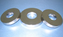
"The huge ring type of sintered Rare earth ndfeb magnets magnets
Key Specifications/Special Features:
1.The most large Ring type magnets, such as F88×F30×15 mm, F125×F50×30 mm;
2.The Magnets with high grade material, such as N35SH,N38SH,N40H,N42H;
3.The Magnets be used in the lines of speaker and motor."
Attachments
Some max SPL vs. Xmax data comparing 10" and 12" dipole midranges on 24" x 48" baffle, with speaker mounted at 36" from floor.
10" = 345 cm2
12" = 530 cm2
FOR 80 Hz
110 db SPL @ 1M
10" = 8.7mm Xmax
12" = 5.6mm Xmax
FOR 120 Hz
110 db SPL @ 1M
10" = 2.6mm Xmax
12" = 1.7mm Xmax
========================
FOR 80 Hz
115 db SPL @ 1M
10" = 15.4mm Xmax
12" = 10.0mm Xmax
FOR 120 Hz
115 db SPL @ 1M
10" = 4.6mm Xmax
12" = 3.0mm Xmax
10" = 345 cm2
12" = 530 cm2
FOR 80 Hz
110 db SPL @ 1M
10" = 8.7mm Xmax
12" = 5.6mm Xmax
FOR 120 Hz
110 db SPL @ 1M
10" = 2.6mm Xmax
12" = 1.7mm Xmax
========================
FOR 80 Hz
115 db SPL @ 1M
10" = 15.4mm Xmax
12" = 10.0mm Xmax
FOR 120 Hz
115 db SPL @ 1M
10" = 4.6mm Xmax
12" = 3.0mm Xmax
Attachments
We are not set up for large neo motors at the moment. Cost is a primary concern as this is a low production design we are talking about here. This midbass if done needs to use as much as possible that is currently on the shelf, and it will be able to use the planned Alnico and Field Coil motors. We can revisit the neo question in the future once we gear up for it, but it will be awhile as it will be a larger investment than anything else done yet by either Lambda or AE.
LineSource said:
For the highest efficiency underhung midrange motor, NdFeB might be worth a prototype test, even with a pre-magnetized ring. If NdFeB saturates the pole steel, a field coil with all of its cost and power supply issues should not yield higher efficiency. Stop global warming with high efficiency NdFeB!
While an underhung motor is a good example where more B is often useful or desired, be cautious in blindly chasing motor strength in the name of efficiency.
The driver Sd and minimum achievable moving mass set practical limits on what sort of efficiency is possible, especially below some lower frequency. Depending on the minimum mass threshold, that could be in the 300-500Hz range. More BL on the same coil will give you a greater calculated sensitivity, but only at higher frequencies, and in an open baffle or sealed design, the increasing motor strength will in fact lower the sensitivity below this effective hinge point.
Moral of the story: Before you start chasing any given parameter or quality be sure to check the ideal thresholds of what is possible. If you want high efficiency (~100dB @ 1W/1m) in an open baffle, you either will have to limit your low frequency expectations or use larger Sd than a single 10" driver through multiples or larger cones.
Nick,
I followed the discussions of current source amps some years ago on this forum and have read Hawksforth's papers on the topic. The advantages are considerable less compression and distortion. I am by far not an expert on driver design, but perhaps you can have important pointers on the following thread: http://www.diyaudio.com/forums/showthread.php?threadid=3889 , look for Thorsten's (a.k.a. Kuei Yang Wang) posts.
Have you considered H- or W-frame and "unipole" "subs" for the lowest freq range of the kits? Ferekidis (you will find some papers on the web) and Kempe have some very interesting investigations concerning maximal baffle width and comparisons between Dipole, Monopole and Unipole, favoring the latter by reasons shown in the papers. I don't know if it would work, but at first glance one could arrive at a unipole sub using little damping on the back of the cone (like aperiodic) and current drive. A unipole commercial version is the Gaithain RL901K ( www.wvier.de/texte/Monopol, Dipol & Unipol.pdf ). Their papers are in German, perhaps in English through AES. If you need a translation I could help.
system & market view . .
Hi Nick
What about aiming for synergy in designs with this sort of similarly high quality & sensitivity tweeter, crossed at c 1600 Hz
http://www.raalribbon.com/products_flatfoil_140-15.htm
RAAL are fwiw liked by (to some degree) Lynn Olson and a number of others
If the Lambda midbass can be just 95 dB/ watt, that'll allow most tube amps. A good SS amp would have dynamics to burn.
Allow the bottom Hz to be the balancing factor, probably (baffle/ box dependent) in the range 100 – 150 Hz. Below that a sub
So 95 dB, 150 – 2000 Hz
By lowering the sensitivity factor to 95 dB, for sound quality better than the JBL 2123 or PHL 3451 or Eighteensound – ie "best in breed"
Cheers
Re: system & market view . .
With a midrange which would mean a 3way design I dont see any point in making a dipole driver with high Qts and weak magnet, it would then make more sense to aim at a low Qts driver with a strong motor, it would roll off by itself at the suggsted frequency
btw, it has been suggested that the RAAL doesnt sound its best crossed low, could be design related though
otto88 said:Hi Nick
What about aiming for synergy in designs with this sort of similarly high quality & sensitivity tweeter, crossed at c 1600 Hz
http://www.raalribbon.com/products_flatfoil_140-15.htm
RAAL are fwiw liked by (to some degree) Lynn Olson and a number of others
If the Lambda midbass can be just 95 dB/ watt, that'll allow most tube amps. A good SS amp would have dynamics to burn.
Allow the bottom Hz to be the balancing factor, probably (baffle/ box dependent) in the range 100 – 150 Hz. Below that a sub
So 95 dB, 150 – 2000 Hz
By lowering the sensitivity factor to 95 dB, for sound quality better than the JBL 2123 or PHL 3451 or Eighteensound – ie "best in breed"
Cheers
With a midrange which would mean a 3way design I dont see any point in making a dipole driver with high Qts and weak magnet, it would then make more sense to aim at a low Qts driver with a strong motor, it would roll off by itself at the suggsted frequency
btw, it has been suggested that the RAAL doesnt sound its best crossed low, could be design related though
Tinitus,
it does make sense if you want the mid driver to cover the human voice freq range, i.e. the range form 80 to 1200 (or 1500 as Linesource writes above), on an OB which does not exceed 2.2 times the drivers effective diameter. How high the Qt should be could be precisely determined with a model and real measurements. How efficient would depend on the target response and complementary drivers. Doing a passive system would have obvious advantages for the usual diy'er with limited resources, at least in the range 80-20K.
I would be much more concerned about the cone employed and forgiving fall off (i.e. break-up, no nasty peaks before and at falloff). At this, hemp cones seem to excel (ToneTuby and Lill' Buddy).
The point where I wouldn't be too stringent is power requirements and excursion. Martin King argued about excursion capabilities on a parallel thread. He has 2 excellent papers on OB design which are empirically founded. The latest one compares baffle mounted "subs" to H-frames and shows the latter gain low freq. extension at the expense of sensitivity, but that is a place where you can easily adapt a good sub (plate) amp with eq if needed, for example the Mommsen modules.
Re: Re: system & market view . .
We would probably not be designing any Dipole or OB kits (I don't really know the difference on these two) Rather we can upload (good) plans anyone else wants to submit or we can include links to any designs.
This 10" is not intended for OB use only, rather I have another use in mind as well.
I would like to see 93-95dB on this driver with a range from low bass to 2Khz as smooth and clean as possible. My personal desire is a simple 2 way with this driver that can play loud in a large room.
We already make Dipole specific motors and this new cone idea could be used there as well. I am thinking of a small doped foam surround with about 12mm mechanical xmax each way would be ideal. The smaller the foam surround the less its resonance becomes an issue and the larger the working cone area.
Hemp is not the only one, there are others. Our regular TD cones don't have much problem either. There is a particular material Roger Russell turned me onto that I plan to test. I will also be testing the same formulation as what will be done with the 8"
swak said:Have you considered H- or W-frame and "unipole" "subs" for the lowest freq range of the kits?
We would probably not be designing any Dipole or OB kits (I don't really know the difference on these two) Rather we can upload (good) plans anyone else wants to submit or we can include links to any designs.
This 10" is not intended for OB use only, rather I have another use in mind as well.
otto88 said:What about aiming for synergy in designs with this sort of similarly high quality & sensitivity tweeter, crossed at c 1600 Hz
http://www.raalribbon.com/products_flatfoil_140-15.htm
RAAL are fwiw liked by (to some degree) Lynn Olson and a number of others
If the Lambda midbass can be just 95 dB/ watt, that'll allow most tube amps. A good SS amp would have dynamics to burn.
Allow the bottom Hz to be the balancing factor, probably (baffle/ box dependent) in the range 100 – 150 Hz. Below that a sub
So 95 dB, 150 – 2000 Hz
By lowering the sensitivity factor to 95 dB, for sound quality better than the JBL 2123 or PHL 3451 or Eighteensound – ie "best in breed"
Cheers
I would like to see 93-95dB on this driver with a range from low bass to 2Khz as smooth and clean as possible. My personal desire is a simple 2 way with this driver that can play loud in a large room.
tinitus said:With a midrange which would mean a 3way design I dont see any point in making a dipole driver with high Qts and weak magnet, it would then make more sense to aim at a low Qts driver with a strong motor, it would roll off by itself at the suggsted frequency
We already make Dipole specific motors and this new cone idea could be used there as well. I am thinking of a small doped foam surround with about 12mm mechanical xmax each way would be ideal. The smaller the foam surround the less its resonance becomes an issue and the larger the working cone area.
swak said:Tinitus,
it does make sense if you want the mid driver to cover the human voice freq range, i.e. the range form 80 to 1200 (or 1500 as Linesource writes above), on an OB which does not exceed 2.2 times the drivers effective diameter. How high the Qt should be could be precisely determined with a model and real measurements. How efficient would depend on the target response and complementary drivers. Doing a passive system would have obvious advantages for the usual diy'er with limited resources, at least in the range 80-20K.
I would be much more concerned about the cone employed and forgiving fall off (i.e. break-up, no nasty peaks before and at falloff). At this, hemp cones seem to excel (ToneTuby and Lill' Buddy).
Hemp is not the only one, there are others. Our regular TD cones don't have much problem either. There is a particular material Roger Russell turned me onto that I plan to test. I will also be testing the same formulation as what will be done with the 8"
MisterTwister said:....
it would be best diy mod ever if we figure out how to make aic coil.
http://www.eighteensound.com/staticContent/technologies/products/aic.pdf
Someone has already posted that article somewhere.
It'd be near impossible for average DIYers to make AIC themselves. That coil is located in the gap, and wound in the little recess aound the center pole piece.
A few things I find interesting in the paper on AIC. Clearly it is a paper written to prove a point and has some bias to it. One thing I see of great interest is the following statement:
"This solution could be further improved in terms of 3rd order distortion reduction using instead of a ring in the gap, a complete sleeve that cover almost completely the pole piece. This solution probably allows for better circulation of eddy currents even at high frequencies where they should tend to concentrate in the upper and lower part of the gap. Incidentally, this add still more complexity to the design and cost more in terms of general efficiency."
That is interesting because the full sleeve on the pole is exactly what we do. They claim it would be better, but yet they don't test against that option. If trying to prove AIC superior in decreasing distortion wouldn't you test against the best possible known option? Secondly, their is no mention as to the thickness of the shorting ring in the gap with that comparison. Quite simply, the thicker the shorting ring, the more effective it is.
They claim in the last section that the shorting ring in the gap had more of a tendency to heat up the pole piece than did the AIC. A full sleeve on the pole would sink even more heat into the pole. This means it is more effective at keeping heat off the coil and lowering power compression, which is a good thing. What confuses me is that they seem to believe pulling heat away from the coil is a bad thing? The first step in dealing with power compression is the immediate need to get heat away from the coil itself.
John
- Status
- This old topic is closed. If you want to reopen this topic, contact a moderator using the "Report Post" button.
- Home
- Loudspeakers
- Multi-Way
- AE Lambda Midbass 10 Project?