"closeness" to the actual PE Safety Earth is of no consequence.
The tie point could be at the other side of the Chassis from the Mains in put socket/cable and it's PE to Safety Earth.
One simply requires a route from exposed conductive part via the Chassis to PE.
Some Chassis have removeable panels. These panels are interlinked with leads to welded lugs. One could have a route that passes from a front panel to the floor panel to the back panel to the PE. That's four areas linked with three cables. It complies.
I have seen exactly this in commercial amplifiers (from a juke box) and even the lid had it's own welded link/cable to the back panel. But what was unusual, the plastic corners used to assemble all the panels into a "box", very effectively insulated each panel from it's neighbour.
Ok thanks. Obviously this enclosure is multiple panels, assembled and screwed together. I will make sure there is a route to the safety earth connection for each. I should have made the PCB mounting holes such that when screwed to their standoffs a connection from ground to chassis was made.
I take it from your response that "exposed" is determined with, for example, the lid of the enclosure off so that the PCBs are accessible.
I take it from your response that "exposed" is determined with, for example, the lid of the enclosure off so that the PCBs are accessible.
Texas Instruments Application Report SLAA412: LDO Voltage Regulator PSRR Measurement Simplified may contain a few gems and helpful tricks, for those who wish to verify that dVout/dVin < -80dB on their own homebuilt voltage regulators.
Thanks. I will take a look. I've spent the last couple of days assembling everything into its enclosure which was a learning curve in itself. Memo to self: Leave more room in the corners for access to interior assembly bolts/nuts. I will try to take some pics in the coming days.
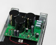
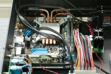
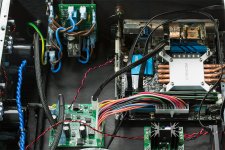
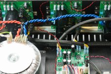
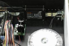
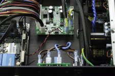
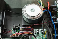
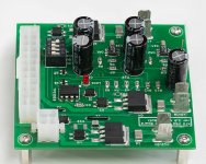
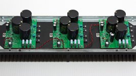
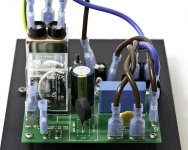
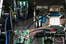
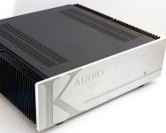
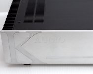
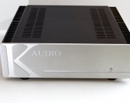
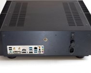
Here's a few pics of the interior. Yes, some of the cabling is overkill. Please anyone, do let me know if you spot things that should be corrected.
Attachments
-
 ATX PSU 2.jpg246 KB · Views: 232
 -
 Internal 11.jpg649.5 KB · Views: 131
 -
 Internal 12.jpg676.5 KB · Views: 120
 -
 Internal 5.jpg654.2 KB · Views: 118
 -
 Internal 2.jpg376.1 KB · Views: 118
 -
 Internal 10.jpg486.1 KB · Views: 212
 -
 Internal 7.jpg610.3 KB · Views: 224
 -
 ATX PSU Control 1.jpg311.7 KB · Views: 230
 -
 ATX PSU 3.jpg298.3 KB · Views: 230
 -
 Soft Start.jpg317.4 KB · Views: 132
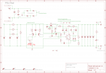
I have one question with respect to Fig 11 from Rod Elliot's article on Voltage and Current Regulators (here). I have reproduced his graphic below for convenience. How should one determine appropriate components for the protection diodes D9 and D10?
Also, if I were to use two of my spare PSU boards in this fashion, the negative rail would have the board's GND plane be the -12V supply and the Vout traces would be GND. Is this reversal of GND plane and traces a problem/bad practice/detrimental to quality?
Also, if I were to use two of my spare PSU boards in this fashion, the negative rail would have the board's GND plane be the -12V supply and the Vout traces would be GND. Is this reversal of GND plane and traces a problem/bad practice/detrimental to quality?
Attachments
These are discussed in Cordell section 15.3.2 "Rail Fuses".How should one determine appropriate components for the protection diodes D9 and D10? (these are the reverse biased diodes between (a) +supply and GND; (b) -supply and GND
I suggest that those diodes should be rated for a current at least equal to the larger of (i) (Vprimary/Vsecondary)*Primary_fuse_current ; (ii) the current rating of the downstream fuses in the DC rails ; (iii) the output current limit value of the voltage regulators
Me, I would use what I have in my junkbox: the FES16DT (datasheet). 200V, 16A, TO220, $1.07 qty=1. It's got a metal tab; maybe you want an all-plastic TO220 instead, since this diode will never get hot.
Thanks Mark. Well spotted. I will try to rectify it.
The audio server has been running continuously for a few days now and seems to be working well. The supply runs a bit warmer than I expected but not hot. There's a faint buzz from the transformer, but it is audible only in a silent room with one's head within a foot or so of the unit. It isn't yet plugged into my Isotek power conditioner. (It will be interesting to see what a difference that makes.)
I'm very happy to finally have this thing running.
I'm enormously indebted to you in particular but also to others who have helped me do this. Thank you.
These are discussed in Cordell section 15.3.2 "Rail Fuses".
I suggest that those diodes should be rated for a current at least equal to the larger of (i) (Vprimary/Vsecondary)*Primary_fuse_current ; (ii) the current rating of the downstream fuses in the DC rails ; (iii) the output current limit value of the voltage regulators
Me, I would use what I have in my junkbox: the FES16DT (datasheet). 200V, 16A, TO220, $1.07 qty=1. It's got a metal tab; maybe you want an all-plastic TO220 instead, since this diode will never get hot.
Thanks. I will take a look at Cordell. I haven't a specific place for these diodes on the PCB and so will have to jerry rig them over the Faston connectors at the output or similar (so something insulated makes sense). I guess I could use spare FFPF30UP20STU which I am using in the rectifier bridge but I was hoping for something smaller. I will have a look around.
Last edited:
The 10A series (and their little brothers the 6A series) are axial lead devices, perhaps more suited to jerry rigging. The VSB1545 is a Schottky super-diode, intended for solar energy applications, rated for 15 amps (!) in an axial lead package.
10A6-T Rectron | Mouser
6A2-T Diodes Incorporated | Mouser
VSB1545-M3/54 Vishay Semiconductors | Mouser
10A6-T Rectron | Mouser
6A2-T Diodes Incorporated | Mouser
VSB1545-M3/54 Vishay Semiconductors | Mouser
I notice an LED next the power switch.
I'd be glad to send you a "breathing" LED driver that slowly ramps the LED's brightness from 0% to 100% and back to 0%. It's an 8 pin thru-hole DIP (3.3V or 5V power supply) that can source 20mA; if your LED needs more you can install an external 2N7000 or BC547 to boost the current. (the IC is a PIC10F222).
Here are some youtube videos that show the basic idea; I would of course personalize the chip to ramp the LED brightness at YOUR selected frequency with YOUR selected min, max, slope1, and slope2.
Breathing LEDs are ever so much more soothing than constant-on, or on/off blinking.
https://www.youtube.com/watch?v=o3j9yZz7GeM
https://www.youtube.com/watch?v=f5BSn9xLXhk
https://www.youtube.com/watch?v=JRkum0bj2zA
Last edited:
Thanks for the offer Mark. I'm inclined, however, to just leave it alone. A slowly pulsing front LED is associated with a computer in sleep. Plus, that part of the enclosure was a nightmare. The small pcb with LED (and its associated resistor) and momentary push to make SMD switch on it was sourced from a Wesena enclosure. It would have been easy enough to replicate. The extraordinarily difficult bit was sourcing a very simple brushed aluminium "button" to sit in the panel. I searched everywhere. In the end I asked Theta Digital to send me a couple as they use them in their Casablanca. It's nothing more than a short rod of brushed aluminium (or some other composite material) with an o-ring in a groove at one end and rounded other end. Of course, the "button" I received from Theta was designed for a thicker panel than this 10mm one and so I had to get it cut down and a new groove cut for the o-ring. A stupidly expensive 1/2 inch or so of metal/composite.
Perhaps a question for Andrew...
For my Wire Bal-Bal headphone amp build's supply I am using two of my PSU modules set for +/-12V and coupled according to Fig 11 here. I selected a 40VA transformer with 2 x 15V secondaries (230V primary). Lots of headroom all round.
I am now looking at the fuse required. At the full rated value of the transformer the secondary current draw is 40/15 = 2.67A or 1.3A per regulator. The load will never get that high.
According to OPC the designer of the amp board (a part of the discussion in which Andrew participated):
I'm running +/-12V so idle losses will be a bit less but let's round it up to 0.6A anyway (there's losses on the PSU module itself due to bleeders if nothing else).
I still get confused when I have a fully balanced amp, with two channels, as to whether both buffers per channel are drawing and hence the potential load is 0.6A per regulator i.e. 1.2A total or just a maximum of 0.6A at any one time.
Either way I think it's clear that the primary (slow blow) fuse can be of small current rating. Vp/Vs = 230/15 = Is/Ip = 1.2/Ip => Ip = 0.078A. 0.6A of secondary current is half that again.
I was looking at Littelfuse slo-blo cartridge fuses (6.3 x 32mm) which fit my fuse holder. 31mA, 100mA, 125mA and up are available. I was planning to use a 100mA one.
Am I making a mistake?
For my Wire Bal-Bal headphone amp build's supply I am using two of my PSU modules set for +/-12V and coupled according to Fig 11 here. I selected a 40VA transformer with 2 x 15V secondaries (230V primary). Lots of headroom all round.
I am now looking at the fuse required. At the full rated value of the transformer the secondary current draw is 40/15 = 2.67A or 1.3A per regulator. The load will never get that high.
According to OPC the designer of the amp board (a part of the discussion in which Andrew participated):
Idle losses are relatively small compared to full power load requirements.
Total current draw depends on the rail voltages, the higher you go in voltage, the higher the quiescent current. See page 8 of the LME49610 datasheet for the graph of current draw vs. BW vs. supply voltage.
In a typical +/-15V setup at idle, with the BW pin tied to V-, you'll be drawing 14mA per buffer and 14mA for the OPA1632. That's roughly 42mA per channel, or 84mA per board.
At full load, the buffers can deliver 250mA peak current per channel, so you'll need to handle peaks of 500mA if you want to be able to run both channels at full power.
It's exceedingly unlikely that you will ever need full power
I'm running +/-12V so idle losses will be a bit less but let's round it up to 0.6A anyway (there's losses on the PSU module itself due to bleeders if nothing else).
I still get confused when I have a fully balanced amp, with two channels, as to whether both buffers per channel are drawing and hence the potential load is 0.6A per regulator i.e. 1.2A total or just a maximum of 0.6A at any one time.
Either way I think it's clear that the primary (slow blow) fuse can be of small current rating. Vp/Vs = 230/15 = Is/Ip = 1.2/Ip => Ip = 0.078A. 0.6A of secondary current is half that again.
I was looking at Littelfuse slo-blo cartridge fuses (6.3 x 32mm) which fit my fuse holder. 31mA, 100mA, 125mA and up are available. I was planning to use a 100mA one.
Am I making a mistake?
The close rated soft start fuse will be 40VA/230Vac ~T200mA
But without a soft start and applying the normal motor/transformer fuse requirement you get 40VA*3/230Vac ~ T500mA for your 40VA transformer.
The maximum continuous AC output current is 40VA/(15+15)Vac = 1.33Aac
If you feed that through a bridge rectifier and then into a capacitor input filter you will find that the maximum continuous DC current rating is roughly half that AC value, i.e. 667mAdc
If you want that transformer to run cool you should operate @ approximately 50% of the max continuous DC rating, i.e. 333mAdc
That current is available from both secondary windings.
A CCS feeding into a Shunt regulator is a continuous DC current.
Be careful you don't overheat your transformer.
The inside is a lot hotter than the outside surface of all that insulation wrapped around the toroid !
Last edited:
Thanks Andrew. I was not aware of the "normal motor/transformer fuse requirement" formula. 0.5A slo-blo it is. I presume I can use these general rules from now on.
Hmm, your second paragraph means I have a lot less headroom in my transformer selection than I thought.
I'm still confused as to the nature of the load with this balanced headphone board. There's one dual op amp and two LME49610 per channel. Each LME49610 has a maximum output current of 250mA. I understand that, because it's a balanced design, both LME49610 (per channel) conduct the current at the same time according to IanAS's comment here. (The quiescent current for the board as a whole is less than 80mA. My PSU board bleeder resistor (R2) and LED and its associated resistor (R14) at the output create a modest quiescent current on the PSU rails itself.)
So do I have (for two channels operating at maximum) '2 channels x 0.25Apk + idle load' for each reg (+ and -) with both + and - regs drawing this current at the same time or is it 4 x 0.25A...? I think the former (i.e. c0.6A pk load on each +/- reg simultaneously) but I confess to being unsure. I know I need to learn more about amplifiers and perhaps a fully balanced design isn't the easiest place to start.
Of course, my headphones will never need full current at 12V but I was thinking 'design for maximum and have plenty of headroom'.
Re CCS feeding into a Shunt reg, only the bias through the op amp output level shifter is fed from a CCS. This is small and only around 8mA. Unless I missing something else.
EDIT: I have just investigated Class T fuses. You recommend a fast blow?
Attachments
Last edited:
- Status
- This old topic is closed. If you want to reopen this topic, contact a moderator using the "Report Post" button.
- Home
- Amplifiers
- Power Supplies
- Adventures with 5A regulated voltage circuits