OK
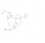
I hook up V+ directely to E, and C
I will use 1k res on B
and 10ohms on C
Can I use 5.17 volts, and still get accurate beta with IC / IB?
Are 1/4 watt resistors OK
A heat sink is no big deal. I plan on making a jig. You know how many I have to deal with.
IF 5v is too much how about 3v, or 1.5v
Thanks Ben
Attachments
Hi Ben,
Transistor checkers often use a 1.5 VDC battery or two. 5V would be better and not cause excessive heat. I typically run my jigs at either 10 VDC or the actual working voltage. Heat sinks are required in that case.
Your base supply will normally supply less than 1 mA (normally tens of uA). Your injected current will be the applied voltage, less the E-B drop (call it 0.55 VDC), all divided by the resistance in series with the base. So you might want to add some resistance in series with the 1K. The 1K resistor exists so you can measure the voltage drop across it.
If you make a jig, a more complicated circuit can be made. What I have shown you can be put together with resistors and test clips. You may need to install a capacitor from the collector to base to prevent oscillation.
-Chris
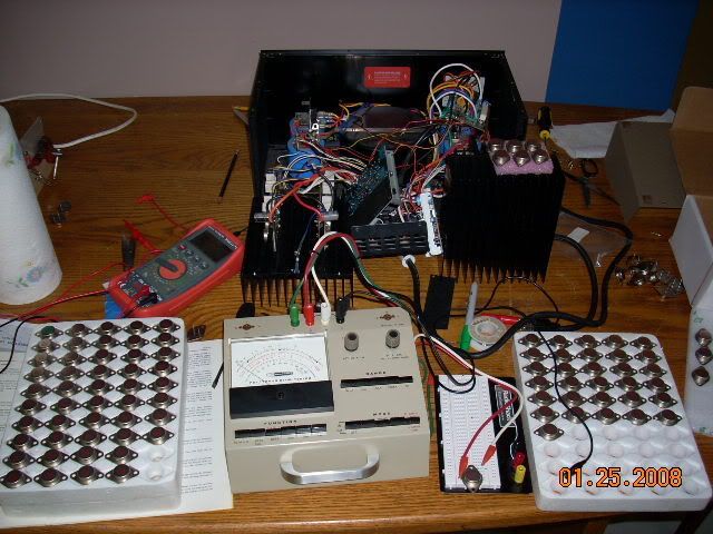
Well I have just about given up on using a jig. I am not sure where I should be testing for the currant. I have fallowed the directions as best I could. I have searched the interenet for something step by step. I have not found one start to finish setup. All I know is when I figure it out I am probally going to slap myself because it is much easier than I am making it out to be.
I am a big ******* retard so I bought this

Heathkit IT-121 FET Transistor Tester and manual
Now all I need is someone to help me read the manual
http://bama.edebris.com/manuals/heath/it121/
Now that I bought this thing should beta = roughly 5?
Heathkit IT-121 FET Transistor Tester and manual
Now all I need is someone to help me read the manual
http://bama.edebris.com/manuals/heath/it121/
Now that I bought this thing should beta = roughly 5?
Hi Ben,
That is also an excellent tester. I have one also. Your unit appears to be in great shape also! Check the battery and switch contacts as you would with any old electronics.
Normally, I would recommend people use the IT-18 as it's simpler and faster to use. The set up procedure is more involved with yours, but not vastly so. The IT-121 should give you accurate numbers.
Now, a beta of 5 is possible, but would not indicate a good audio output transistor. I might see that number on old horizontal output transistors, but not on your parts. Can you check to see if you missed a multiplier? Your beta might actually be 50, on the low side of what I normally see with your transistors. I would expect figures in the range of 60 ~ 90 for the bulk of those. You will see some "fliers" outside this range.
If you have the manual, read it through a couple times. Especially the "operating" section. If you are at all like me, I can't read well off a computer screen. Therefore, I print most of my manuals off. The operation and use sections at the very least. This might be a good idea for you. Keep the instructions with the tester.
-Chris
Hi Ben,
Yes, you will find that your figures will agree reasonably closely with those obtained using a jig at higher C-E voltages and currents. Matches made with this tester will also correlate well from my experience. Beta match is most important at low currents anyway as emitter resistors will force current sharing at higher currents.
Life is beautiful. Your figures are in the range I would have expected to see.
-Chris
I cranked the tester up to 1amp, and there was a little difference I have been able to separate a little better. It is like these things were ordered matched. I have tested some other transistors I have around, and after going through about 150 so far I can't believe how close these are. At 1 amp the beta is reading 80-81 on 90% of these transistors. Just curiosity how close does beta have to be? Would 78 play nicely with 81? I am not worried about this project, just thinking about testing other amps outputs.
Thanks
Ben
Thanks
Ben
Hi Ben,
I might say yes to a 5R1 or a 5R6. Possibly 4R3 would be okay too. I think 8R2 would probably burn out soon. 4R7 is a standard value, so I suggest you order the correct part. 8R2 might work for temporary testing, but I can't say how long it might last as it will dissipate more heat than the original value.
-Chris

Hey Chris I went through that 2 years ago. The voltage is 1 vdc no load, but it is low currant .24 amps at 4 ohms
I should have done a voltage test under load @ idle, but no load .9v @ 4ohms is .2 watts. I have done the boards three times. First with RS spray cleaner with a brush, and the next two times was with simple green 10 parts water, 1 SG. I remove the bias pot, and brushed the snot out of them. I replaced all electro caps on the boards. I will dig the post, but there was an issue with voltage if I remember correctly at the OP-Amps. Well I am listening to some Allison Krause right now, and I am extremely pleased nothing else blew
Thanks
Ben
Hi Ben,
Even though you have cleaned it, that coating is still on the boards. DC offset is not normal for these amps and is not acceptable. I'm really sorry to say that the PCB still needs to be cleaned.
Some boards I have done have taken a few cleanings and I don't stop until the fluid is gone.
Sorry Ben, not what you wanted to hear.
-Chris
ben62670 said:I have done it 3 times! twice very thorough, and properly! Per your instructions minus the ultrasound. There has not been any change at all with the cleanings. No improvement at all
Well anyways I hooked it up, and was driving a 2.6ohm load to 116db today with it.
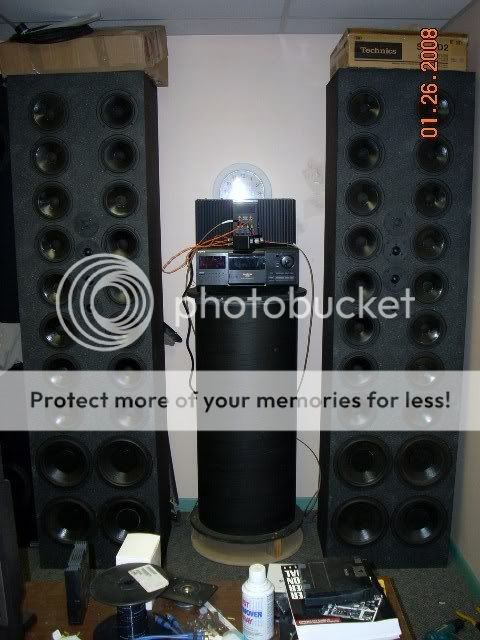
WOW!
Nice System! Those speakers must sound awesome, and all those drivers...... Also, how did you drive a 2.6 ohm load?
Is that a subwoofer in the middle?
I have 8 8 ohms in series parallel for 4 ohms in the stereo array.
Also same deal in the dimensional array. This would yield a little less than 2ohms, but I have an inductor that is 1.9 ohm in line with the ground on the dimensional array. What happens is the dimensional array gets the signal, and there is a cable that runs from the dimensional arrays ground out to the opposite speakers dimensional array. What this does is add an out of phase signal goes to the opposing speakers dimensional array. These big speakers just seam to disappear. The sound stage extends far past the outside of the speakers. Carver did this with holography, and what I did was copy Polk Audio's SDA speaker design.
http://www.polkaudio.com/homeaudio/products/srs12tl/
These are the white papers on SDA technology
http://www.polkaudio.com/downloads/whitepapers/SDA_WhitePaper.pdf
Page six shows it best
BTW
I just reached 125db with Fleetwood Mac's worlds turning bass riff
Hey you are in FLA too!
Where about?
- Status
- This old topic is closed. If you want to reopen this topic, contact a moderator using the "Report Post" button.
- Home
- Amplifiers
- Solid State
- Adcom GFA-585 Blown 20w 4.7ohm on soft start board