I think Ben is under the impression that there are limitless numbers of possible replacment output transistors for that amp. 20 years ago there were tons of great TO-3 transistors to choose from. Now, the TO-3 is almost an obsolete part due to the hassle of mounting it.
To quote anatech:
To quote anatech:
In the old-fashioned TO-3 case, these are just about the only choice left for high-powered bipolar amps.Use MJ15024/25 or MJ21193/94 or MJ21195/96
Hi EchoWars,
")
Hi djk,

I'm sure you could point out some other specs.
-Chris
At least we've been blessed with good parts. If all we could use were MJ15015 and MJ15016, repairing an amp wouldn't be worth the trouble for the result.In the old-fashioned TO-3 case, these are just about the only choice left for high-powered bipolar amps.
Hi djk,
Agreed. Many people have not read the specs, have they? Things like vibration resistance and radiation hardening does nothing for an audio part (unless it's in a subwoofer amp mounted in the sub box on the space station).I deal with mil-spec parts every day, you don't want them.
I'm sure you could point out some other specs.
-Chris
I wouldn't complain if On-Semi decided to release a new TO-3 transistor with the SOA of the MJ211293 and 94, and an ft of 10MHz...anatech said:Hi EchoWars,
At least we've been blessed with good parts. If all we could use were MJ15015 and MJ15016, repairing an amp wouldn't be worth the trouble for the result.
Yes, things could be worse...but they could be better too.
OK I have some numbers
The closest 5 of 10 I had was all tested with 5.17 volts in, and 75, and 10 ohm R's
.688vin=4.05v
.687vin=4.06v
.686vin=4.07v
.686vin=4.09v
.677vin=4.10v
This was with MJ21194g's
That last one sucked, but was as close as I could get
On the MJ21193g's it was much better
all were 4.37 out, and
4 @ .782vin
1 @ .779vin
Thanks so much for the reply. I was going batty here.
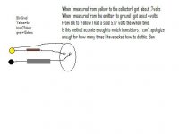
I used a 5.17 volt power suply(rock steady... a volt meter was on it the whole time).
A 10ohm 25watt resitor on the emitter to ground, and 75ohm 5 watt on the other leg from source power. All the volatges listed were taken under load fom the same power suply.
The .68, and the .78 volts was between the resitor, and the MJ's
The 4 volt specs were accross the load resistor (10ohms) after the emitter.
Thanks Ben
So you mean collector to + of supply, base to + through 75 ohms and emitter to - through 10 ohms?
I'm afraid that test won't tell you much except Vbe.
I think you should do what Chris suggested, match for hFE. I guess this should be done at the bias current used. (Is this correct Chris?)
BTW, I'm interested in knowing what the power supply voltage used in the amp is, what resistance the emitter resistors are, if it uses base resistors and what the bias current is. Is there a schematic somewhere maybe?
Regards,
Joakim
Hi Joakim,
-Chris
Yes, exactly. I posted a circuit that makes this much easier to do.I think you should do what Chris suggested, match for hFE. I guess this should be done at the bias current used. (Is this correct Chris?)
-Chris
Hi Ben,
That is not going to do what you want. hFE is the ratio of collector current to base current. What you should do is use a resistor in the collector lead so you can calculate the current. 1 ohm makes things easy. If you have a poor quality meter, you may want to use 10 or 100 ohms to reduce your error. Then you adjust the current into the base to make the collector current whatever value you are testing at. 10 mA would not be unreasonable, 100 mA with a heat sink. Once you have set the collector current, measure your base current. IC / IB = beta.
Since you are setting IC the same with all the transistors, the C-E voltage will also be the same. No worries.
So, how to set IB? Use another resistor (about 1 K) in series with the base. Then you can either use a pot to your collector supply set up as a rheostat, or use a power supply and vary the voltage. You can put another resistor in series with the base to reduce the current. You need the 1 K (or whatever) to measure the base current. Temperature of the transistor will change the readings. That's why the lower currents might be better. Pulsing would work but that is a little beyond the scope of this discussion for your purposes.
-Chris
- Status
- This old topic is closed. If you want to reopen this topic, contact a moderator using the "Report Post" button.
- Home
- Amplifiers
- Solid State
- Adcom GFA-585 Blown 20w 4.7ohm on soft start board