What USB chip do you want to use, PCM2707?Ad1865 by me is a great chip, and natural sound close to anlalog
Using I2S for AD1865 can not be, and Ad1865 will be able to use 24bit. I'm also working on a version using the I2S and USB inputs for ad1865, when results will be reported later.
I'll try previous versions of VZS.
As AD1865 is a 18bit DAC so it cannot convert 24bits correctly. If you clock in a 24bit LSBJ data stream it will loose 6 MSB bits as it has the LSB bits first.
I wonder if its possible to use two AD1865 in parallel, one would convert 18 MSB bits and the other the remaining 6 LSB bits then sum their output. Of course a minor digital interface is needed for this job.
What USB chip do you want to use, PCM2707?
As AD1865 is a 18bit DAC so it cannot convert 24bits correctly. If you clock in a 24bit LSBJ data stream it will loose 6 MSB bits as it has the LSB bits first.
I wonder if its possible to use two AD1865 in parallel, one would convert 18 MSB bits and the other the remaining 6 LSB bits then sum their output. Of course a minor digital interface is needed for this job.
no need Parallel Ad1865, it is expensive, Ad1865 can convert 24bits, if use 74HC164D. it ad more 6 bits.
http://www.datasheetcatalog.org/datasheet2/e/0l5glttjoy0dhlxticge3ilteyfy.pdf
USB DAC?? PCM2707, it is popular, it easy to make it!
You use it??? or no??
Last edited:
I see... I thought you want to convert true 24bits with AD1865. The simple converter I posted in #293 is doing just that. It uses two 74HC164 to shift the I2S data stream by 13 clocks and some reclocking to have everything in sync.no need Parallel Ad1865, it is expensive, Ad1865 can convert 24bits, if use 74HC164D. it ad more 6 bits.
http://www.datasheetcatalog.org/datasheet2/e/0l5glttjoy0dhlxticge3ilteyfy.pdf
USB DAC?? PCM2707, it is popular, it easy to make it!
You use it??? or no??
Yes, I want to try PCM2707 after I test that everything is working.
Hmmm... I could modify the VZ dac board to support USB input as well, so it would have 2 SPDIFs, 1 I2S and 1 USB

I know its popular but after reading this thread about PCM2706 and how noisy its MCK looks like compared to CS8412... I don't knowUSB DAC?? PCM2707, it is popular, it easy to make it!
DIYHiFi.org • View topic - The Price of Progress ? USB Jitter
Maybe PCM2707 is better but using a very good external clock would be the best. Only one would be limited to the frequency of the clock.
What a name, I thought first that you copy-paste-ed something wrongly
I don't know this chip, but I would ask the same question about TAS1020B. This seems to have I2S output.
A high-end brand used it in their own product but they used some licensed software to have asynchronous USB.
Probably the good old PCM2707 will be the first to try
Last edited:
What a name, I thought first that you copy-paste-ed something wrongly
I don't know this chip, but I would ask the same question about TAS1020B. This seems to have I2S output.
A high-end brand used it in their own product but they used some licensed software to have asynchronous USB.
Probably the good old PCM2707 will be the first to try
That is good:
TAS1020B
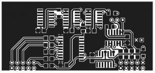
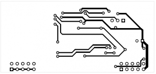
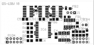
24bit I2S to 18bit LSBJ
Here comes the "simple" converter from 24bit I2S to 18bit LSBJ.
!!! IMPORTANT!!!
Note that this converter uses a 256 x fS master clock to reclock the outgoing signals to have everything in perfect sync (see post #263 in this thread).
Most I2S out devices (e.g. CS8414 or PCM2707, TAS1020B) have 256 x fS master clock available but the I2S bus specification does not specify this signal.
Would be great if somebody could review the schematics and PCB
!!!! The images are not scaled to the previous DAC images
Attachments
Last edited:
Hi, I hope someone could give me a hand with a grounding problem of my new AD1865 raindrop_hui-dac with basic lampizator on-board mods:
ad1865 - this is my first diy'ing.
On lampizator website it's said:
"The digital input RCA is installed with a complete bypass of digital input transformer as well as the input buffer chip. I went directly by silver wire - from RCA hot to CS pin 9 (Rxp) , and from cold RCA to CS8414 pin 10 (Rxn)"
When I connect the RCA hot to pin 9 (Rxp), dac gets the signal and plays music quiet and high frequencies "resonate". When I also connect the cold RCA to CS8414 pin 10 (Rxn) as should, the signal dissapears and nothing plays. Any ideas where to start looking for the problem?
Hi, I hope someone could give me a hand with a grounding problem of my new AD1865 raindrop_hui-dac with basic lampizator on-board mods:
ad1865 - this is my first diy'ing.
On lampizator website it's said:
"The digital input RCA is installed with a complete bypass of digital input transformer as well as the input buffer chip. I went directly by silver wire - from RCA hot to CS pin 9 (Rxp) , and from cold RCA to CS8414 pin 10 (Rxn)"
When I connect the RCA hot to pin 9 (Rxp), dac gets the signal and plays music quiet and high frequencies "resonate". When I also connect the cold RCA to CS8414 pin 10 (Rxn) as should, the signal dissapears and nothing plays. Any ideas where to start looking for the problem?
I also tried what you have done with raindrop board. I believe there is still something else in the circuit that is affecting the connection. Remember as I recall the Lampizator "twists" some parts off the board. On a positive note I now that direct connecting works. I have done this on my Ciuffoli/Quanghao board. To my ears direct connect is the way to go.
I also removed the digital input transformer and digital input buffer chip as adviced. It think that the coaxial RCA cold may be shorted to RCA hot, hence the problem. Could the chip have been overheaten when soldering and cause this problem? (I cant see any other possible problem source)Remember as I recall the Lampizator "twists" some parts off the board..
I also tried what you have done with raindrop board. I believe there is still something else in the circuit that is affecting the connection. Remember as I recall the Lampizator "twists" some parts off the board. On a positive note I now that direct connecting works. I have done this on my Ciuffoli/Quanghao board. To my ears direct connect is the way to go.
Did you mean you bypass the digital transformer on the Ciuffoli/Quanghao board?
Did you mean you bypass the digital transformer on the Ciuffoli/Quanghao board?
yes I did > I go straight to pins 9 and 10
yes I did > I go straight to pins 9 and 10
May I ask a dump question? What's the purpose of the digital transformer before the CS8414?
Another dumb question: if the transformer is in place, it should make no difference if the signal is customer or TTL.
YeS! may be
** I think the transformer is for galvanic isolation **
A small update to my ad1865nos v.1.0 problem: Coax hot is connected directly to CS8414 pin 9 (RXP) and when I connect the coax cold to pin 10 (RXN), signal dissapears.
But: if I connect coax cold to CS8414 pin 8 (DGND), music plays as it should.
Pins 8 and 10 are connected in the pcb as: pin 8 -> ground -> capacitor 0,074uF -> pin 10. The capacitor between pins 8 and 10 should be fully functional. What could be the problem when connecting coax directly to pin 10?
But: if I connect coax cold to CS8414 pin 8 (DGND), music plays as it should.
Pins 8 and 10 are connected in the pcb as: pin 8 -> ground -> capacitor 0,074uF -> pin 10. The capacitor between pins 8 and 10 should be fully functional. What could be the problem when connecting coax directly to pin 10?
Are you talking about the pcb v1.0 I designed (VZS NOS DAC v1.0) or Quanghao's Dac End2 - first version with separate PSU and DAC boards ?A small update to my ad1865nos v.1.0 problem: Coax hot is connected directly to CS8414 pin 9 (RXP) and when I connect the coax cold to pin 10 (RXN), signal dissapears.
But: if I connect coax cold to CS8414 pin 8 (DGND), music plays as it should.
Pins 8 and 10 are connected in the pcb as: pin 8 -> ground -> capacitor 0,074uF -> pin 10. The capacitor between pins 8 and 10 should be fully functional. What could be the problem when connecting coax directly to pin 10?
Sorry forgot to mention, my version is this one:Are you talking about..
AD1865 NOS DAC
And the schematic:
http://a-ling.net/alweb/hifi/ad1865_dac/ad1865.pdf
As you can see, both CS8414 pins 8 and 10 are normally connected to ground (pin 10 via a capacitor). Music can be heard only when coaxial cold is connected directly to pin 8, not to pin 10 (RXN) as it should.
Last edited:
- Status
- This old topic is closed. If you want to reopen this topic, contact a moderator using the "Report Post" button.
- Home
- Source & Line
- Digital Source
- AD1865 the best DAC