This might be usefull.
http://www.steenduelund.dk/download/duelund-filter.pdf
http://www.steenduelund.dk/download/duelund-filter.pdf
The schematics from post #80 are not the Lipshitz-Vanderkooy topology.
The 2nd order one behaves exactly like a Linkwitz-Riley. The 4th order one is a little like the LR4 but it has a smoother phase-shift.
But there are indeed some active speakers out there that use analog implementations o Lipshitz-Vanderkooy or similar.
Regards
Charles
The 2nd order one behaves exactly like a Linkwitz-Riley. The 4th order one is a little like the LR4 but it has a smoother phase-shift.
But there are indeed some active speakers out there that use analog implementations o Lipshitz-Vanderkooy or similar.
Regards
Charles
My 2 cents.
The subtracted response of a 2nd or 3rd order highpass is a 1st order lowpass with a hump around the crossover frequency. A simple 1st order lowpass filter with a bit of overlap will yield a very good approximation to this.
Remember, in practice, most quality drivers still have a response +/- 2dB, and we rarely sit in the optimum position, so we shouldnt be overly concerned with trying to exactly reproduce that subtracted signal - the 1st order approximation with overlap is near enough in practice. The final frequency response will still be +/-2dB, +/-20 degrees.
This is the approach I've always used and so far havent been convinced the added complexity of true subtractive filters or filler drivers is warranted. If someone can convince me otherwise ... ;-)
This is the approach I've always used and so far havent been convinced the added complexity of true subtractive filters or filler drivers is warranted.
Why should a subtractive crossover add complexity ?
Regards
Charles
phase_accurate said:
Why should a subtractive crossover add complexity ?
Regards
Charles
It certainly isnt as simple as a 1st order crossover and it cant be done passively.
It can be discussed if active really adds complexity. Since this thread is about ACTIVE subtractive crossovers then there is no added complexity at all if you compare them to other active crossovers !
Apart from that - they can of course be done passively as well but you would have to sacrifice some efficiency !
And there simply exist NO real 1st order crossovers, only approximations.
Regards
Charles
Apart from that - they can of course be done passively as well but you would have to sacrifice some efficiency !
And there simply exist NO real 1st order crossovers, only approximations.
Regards
Charles
For those who wonder how this can be done:
http://www.musicanddesign.com/icta.html
Here is one of countless possible solutions. It works by subtracting the highpass part from unity.
It is also possible to take driver response(s) into consideration.
Regards
Charles
http://www.musicanddesign.com/icta.html
Here is one of countless possible solutions. It works by subtracting the highpass part from unity.
It is also possible to take driver response(s) into consideration.
Regards
Charles
Attachments
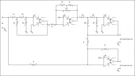
I think I still owe you the answer how C3 is determined. It can be calculated by
C3 = Q1 * Q2 / (2 * Pi * R * (Q1 * f2 + Q2 * f1))
whereas
Q1 = Q value of first 2nd order highpass around U1
Q2 = Q value of second 2nd order highpass around U3
f1 = pole-frequency of first 2nd order highpass around U1
f2 = pole-frequency of second 2nd order highpass around U3
Those "skilled in the art" may even omit the OP-AMP of the first highpass by doing this passively - if at least one of the invloved highpasses has a Q of 0.5 or lower.
The steepest slopes and the narrowest overlap are achieved when the two pole frequencies are equal and the Q values high. But then the humps can get excessively large.
The humps get smaller in amplitude when the pole-frequencies are unequal and the Q - values low. But this goes at the cost of larger overlap and shallower slopes.
One possible method to take driver response into consideration is the following:
Considered we have a midrange in a closed box (the most usual situation) and the woofer's natural response shows some reasonable overlap into the midrange's working range - then we simply dimension the second highpass such that it mimics the midrange's in-box response (which may even be an electronically altered response). The signal going to the midrange amp is then taken from the otput of U2. This way a reasonably flat summed response can be achieved. In order to work well a D'Appolito configuration should be used as mentioned by John K.
That's the reason why I personally use a lower-order subtractive approach with my Manger combination. D'Appolitos with Mangers are quite unsightly.
Regards
Charles
phase_accurate said:For those who wonder how this can be done:
http://www.musicanddesign.com/icta.html
Here is one of countless possible solutions. It works by subtracting the highpass part from unity.
It is also possible to take driver response(s) into consideration.
Regards
Charles
The quoted crossover presented for the ICTA is not a subtractive crossover.
The quoted crossover presented for the ICTA is not a subtractive crossover.
Hi John
I didn't claim this. I just showed a possible way to do it. I guess that you may most probably do both branches seperately.
An intermediate solution between both would be the use of a fourth-order state-variable filter of which the outputs are summed accordingly.
A way of doing it with seperate branches would be the use of my aforementioned first two filter stages (around U1 and U2) for the midrange. For the woofer one would use two biquadratic filters in series (this way the inherent lowpass function of the woofer can be taken into account in an elegant fashion).
It doesn't matter HOW it is done actually. If you achieve the same acoustic transfer function for a given driver setup then the electric filter function will be the same - independant of how it was achieved. What counts in the end is that we derive a pair of trasfer functions by splitting a transfer function consisting of equal numerator and nominator.
Regards
Charles
I guess maybe we are talking of different things. Implementation is one thing, derivation is another. It seemed to me that the topic was about transfer functions where the HP section was derived by subtracting the LP TF from the input (TF = 1.0) or from a delayed version of the input (Vanderkooy and Lipshitz). In that sense, this is not the way the ICTA x-o is developed, although for any TP crossover the 1. - LP = HP. How the TF is implemented is a separate topic.
The consideration given to the ICTA crossover was that both the HP and LP sections must be minimum phase so they are easily implemented with analog circuitry. What I have done there isn't really new, but it was something I think was discarded originally due to the very poor polar response. There is a hole family of these higher order TP crossover, both symmetric and asymmetric that are easily developed and with a proper driver/baffle geometry and crossover point they can yield, as I show on the ICTA page, very good polar response. I'm adding a discussion of them to my site.
The consideration given to the ICTA crossover was that both the HP and LP sections must be minimum phase so they are easily implemented with analog circuitry. What I have done there isn't really new, but it was something I think was discarded originally due to the very poor polar response. There is a hole family of these higher order TP crossover, both symmetric and asymmetric that are easily developed and with a proper driver/baffle geometry and crossover point they can yield, as I show on the ICTA page, very good polar response. I'm adding a discussion of them to my site.
Work in progress.
http://www.musicanddesign.com/icta_cross.html
I'll try to add something about a 3-way soon.
http://www.musicanddesign.com/icta_cross.html
I'll try to add something about a 3-way soon.
thanks for the update
John,
Thanks for the update on the ICTA project. It looks like you've got some traction, and will be ready to start settling on your configuration soon")
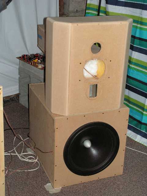
BTW, I just completed the second-round implimentation of your TPSD approach on my 'Gecko' three-way speakers. So far the technical results are excellent. I have only listened a bit, but my initial reaction is that it is quite promising. I had implimented the TPSD early-on during the development of the Geckos, but I was not very familiar with the speakers at the time, so there were other issues that were too severe to hear the benefit of the TP solution.
I'll have a much better impression of the effectiveness in few weeks.
Edward
john k... said:Work in progress.
http://www.musicanddesign.com/icta_cross.html
I'll try to add something about a 3-way soon.
John,
Thanks for the update on the ICTA project. It looks like you've got some traction, and will be ready to start settling on your configuration soon
BTW, I just completed the second-round implimentation of your TPSD approach on my 'Gecko' three-way speakers. So far the technical results are excellent. I have only listened a bit, but my initial reaction is that it is quite promising. I had implimented the TPSD early-on during the development of the Geckos, but I was not very familiar with the speakers at the time, so there were other issues that were too severe to hear the benefit of the TP solution.
I'll have a much better impression of the effectiveness in few weeks.
Edward
BTW, I just completed the second-round implimentation of your TPSD approach on my 'Gecko' three-way speakers. So far the technical results are excellent.
Since you posted a little OT here you do at least owe us some details !
How did you implement the TPSD ? In the digital domain ? Analog ?
What crossover frequencies ?
What driver arrangement ?
Pictures ?
Measurements ?
Regards
Charles
phase_accurate said:
Since you posted a little OT here you do at least owe us some details !
Off topic??? I think NOT!
I am using an Active Sutractive XO! Seems spot on topic to me...
Anyway, I WILL answer all your questions, but I haven't got time right at the moment. I'll post again later today.
Best Regards,
Edward
Some details on the Gecko system
Charles, et al.
Ok, here are the answers to the questions which you had...
The TPSD is implemented in the digital domain with minimum phase filters and delays.
The xover frequencies are ~350 and ~3500
The driver arrangement is fairly classic W--MT
Here's a picture of the Gen II prototype during assembly:
Here is a measurement:
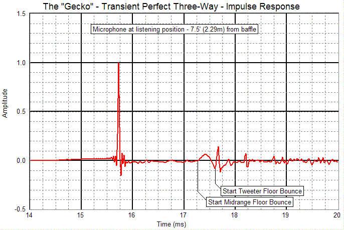
And...
To follow up on my comment to johnk the other day - I have listened to the TP version for a few hours and I believe that the TP version is audibly better. I still have to do a bit more with the FR, but I feel that I have made another forward step with the Gecko system.
Edward
phase_accurate said:[snip]
How did you implement the TPSD ? In the digital domain ? Analog ?
What crossover frequencies ?
What driver arrangement ?
Pictures ?
Measurements ?
[snip]
Charles, et al.
Ok, here are the answers to the questions which you had...
The TPSD is implemented in the digital domain with minimum phase filters and delays.
The xover frequencies are ~350 and ~3500
The driver arrangement is fairly classic W--MT
Here's a picture of the Gen II prototype during assembly:
Here is a measurement:
And...
To follow up on my comment to johnk the other day - I have listened to the TP version for a few hours and I believe that the TP version is audibly better. I still have to do a bit more with the FR, but I feel that I have made another forward step with the Gecko system.
Edward
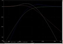
Below you will see the reason why I use the lowest order constant voltage crossover that is possible with my Manger combination:
The yellow and the blue trace are for a 3rd order HP / 2nd order LP target function.
The green and red are for the 2nd order HP and 1st order LP crossover.
One can clearly see that the humps of the higher-order crossover are greater - increasing the need for amp power. I.e. the lower order one is down by 2 dB approx at the crossover frequency - while the higher order one crosses over at + 1 dB approx.
The damping of the lower-order crossover is better within one and a half octave from the actual crossover frequency (on each side).
The slopes of both types can of course be made steeper but that would come at the cost of a further increase in power demand.
The steeper slopes may well reduce IMD and FMD but it is open to what extent this advantage is again given up by the increased power demand around the crossover frequency.
When it comes to transient accuracy, lobing and power demand there is nothing that could compete with the TPSD approach. But this would have to be implemented in the digital domain - otherwise it will only have constant group-delay up to a certain frequency.
Regards
Charles
Attachments
phase_accurate said:With this driver arrangement you'd better keep your digital TPSD crossover because you will have too much lobing with a delay-less constant-voltage TP crossover.
Charles,
Prior to implementing the TPSD version, I have been using a classic LR4 crossovers - with (digital) delay to time-align the drivers. With the delay, I can steer the symmetric LR4 lobe right at the listneing position - in spite of the driver arrangement. I carefully selected the driver layout to improve bass response (due to reinforcement from the floor) and reduce the floor-bounce suck-out.
Edward
- Home
- Loudspeakers
- Multi-Way
- Active Subtractive XOs