phase_accurate said:
Flat amplitude AND phase response !
Regards
Charles
but according to what you discribe (less then -3db crosspoints, within 100 degrees phaselag around cross) it hasn't....
The total acoustical amplitude and phasesum, is a combination of amplitudes and phases of the two drivers, period.
Your whole system (from your added schematic) makes a phase jump with going from the low to the high driver. Look at your high out, it sees a standard higpass-filter, so group delay is added for that output.
Normally you compensate with an added allpass (from the fullrange-feed to the neg. summingnode) but you decided to compensate for the low with the extra 1st order in an extra sumnode. All nice, nothing about that, this still is compensation for the group delay of the high section, so it has group delay/transient-disturbance/is not phaseflat.
Off axis, another (physical) jump from the one driver to the other is added, causing substantial vertical lobing, if driver distance is substantial compared with crossfreq/wavelength.
If you use your filterschematic you can have the benefit of less added lobing due to the vector/filter mechanism, but then, in my opinion it has to be -6dB crosspoints, and if you have -3 to get flat response it just isn't phase-flat as you mention.
I think you'll get a good phase response with a (for instance 4th order) linkwitz low-pass, in series with an allpass that is compensating in the passband for the delay-change thats happening (if you go from low freq. towards the crossfrequency), and so giving an almost constant delay in the passband. Do vice versa with the opposite filter (you have to invert this allpass probably) et voila. You also have a steeper filter compared with the subtractive one.
sorry still not convinced
")
Hi Dokter dB,
Sorry to interrupt.
Charles has done the math right. Active subtractive crossover are flat in both phase and amplitude.
Yes, the ordinary high pass section have group delay from its transition band down to its stopband. Subtraction circuit compare this signal with the original input signal and do the following corrections:
1) In the HP passband:
The HP section has no delay and its amplitude is the same as the input signal. There is no difference between these two signals, so the subtracted LP section has no output.
2) In the HP transition band:
The HP section has some delay and its amplitude is smaller than the input signal. The subtraction circuit first produce a signal, which has the same amplitude and amount of delay as that of the HP section, but with opposite polarity. Then produce another signal with no delay and has the same amplitude as the input.
3) In the HP stopband:
The HP section has delay but the amplitude is very small. This is similar to the case in transition band, except that the opposite polarity signal generated is now very small in amplitude and its visibilty diminished. The subtracted LP section is thus practically the same as the input.
In another word, subtractive crossover correct the group delay (or phase shift) by first cancelling the delayed signal and then replacing it with the undelayed one. So the summed response is flat in amplitude and has no phase shift.
Note that in the transition band, the subtracted ouput section consist of two components in the same frequency, one has delay and one has not. That's why there is a bump around the crossover frequency.
The problem with real world subtractive crossover is the first order slope in the subtracted ouput section and the wide frequency overlap. Few speaker drivers can handle this.
The all-pass delay network in lipshitz & vanderkooij's paper is aim to shape the bump in the transition band, also it uses an ordinary LP section and subtract out the HP. But that is another story.
thanx banana, that is a clear explanation.
Still didn't figure out how it exactly behaves so I started reading/searching on the web and found this:
http://www.geocities.com/kreskovs/new-xooz1.html
excel sheet about it
The impulse/step response shows about everything....
actually this explains that it indeed works (but a bit difficult with the long delays in case of analog) .
Never knew it was such an interesting topic, and that there is so much to do about it..... I'm gonna read some on this for the coming week.....
Good luck with the building of the manger filter guys
Still didn't figure out how it exactly behaves so I started reading/searching on the web and found this:
http://www.geocities.com/kreskovs/new-xooz1.html
excel sheet about it
The impulse/step response shows about everything....
actually this explains that it indeed works (but a bit difficult with the long delays in case of analog) .
Never knew it was such an interesting topic, and that there is so much to do about it.....
I'm gonna read some on this for the coming week.....Good luck with the building of the manger filter guys
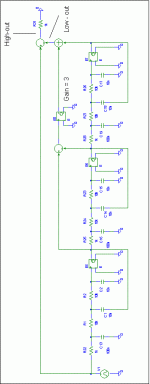
I once mentioned that it is possible to build symmetric 3-rd order subtractive crossovers. They come at a price though: Increased complexity, increased overlap and larger humps (though they can be made a little flatter by using a "flatter "3rd order filter type).
Below you will find the circuit. Simulation results will follow.
Regards
Charles
Below you will find the circuit. Simulation results will follow.
Regards
Charles
Attachments
The Pass website has been redesigned (looks nice BTW) and it can be found under:
http://www.passlabs.com/downloads/articles/phasecrx.pdf
Regards
Charles
http://www.passlabs.com/downloads/articles/phasecrx.pdf
Regards
Charles
Although the following type of x-over isn’t actually subtractive I will post the info here because their main target is the same: Perfect signal summation in time- and frequency- domain.
A while ago I stumbled upon a patent that was taking NFB after the various branches of a passive crossover in order to improve temporal and frequency-response behaviour. The main trick hereby is to NOT OVERDO IT. That means filters shouldn’t be too steep or have too high an order, they shouldn’t have poles with too high a Q value and they should overlap significantly.
Or in other words: Summed phase- and amplitude- behaviour should be fairly decent from the beginning, otherwise the following could happen:
http://www.diyaudio.com/forums/showthread.php?postid=347173#post347173
One patent that uses it is the following, it is obsolete BTW due to non-payment of the annual fees:
http://v3.espacenet.com/origdoc?DB=...212696&DOC=ce973ee58c45feb66f2ceca97118bf8f36
Another one is from ABAKUS rieder (http://www.abacus-electronics.de/) and is basically the same thing:
http://v3.espacenet.com/origdoc?DB=EPODOC&IDX=DE4418360&F=0&QPN=DE4418360
I then thought why not apply this to active filters in order to achieve phase- and amplitude- linearity of the summed signal ? I did some simulations with this topology and the results look useable. These filters still have the humps that we know from the subtractive filters. They show first-order behaviour in the crossover area but approach the steepness that we expect from their order as we move further from the crossover point. One can’t build filters that are as steep in their crossover area as 8th-order LR or whatever by using this topology. If one wants really steep AND phase-accurate crossovers then he must definitely resort to digital FIR filters.
But the x-over-type in question would still allow some room for individual driver EQ-ing (which isn’t easily achieved with the nth/1st order asymmetric subtractive crossovers because most of the necessary EQ-functions are of 2nd order at least). The general requirements regarding out-of-band -behaviour and -capabilities for the drivers are still the same ones as for other topologies (that are trying to achieve transient improved behaviour) but they are a little relaxed compared to other solutions.
It would even be possible to EQ-out driver errors with such a topology, by using filters that emulate driver behaviour in the NFB branches. But as always: DON’T OVERDO IT !!!
I think this is enough to make some of you curious. I will post a simulation example of a third-order crossover later on.
Regards
Charles
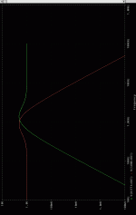
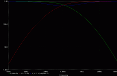
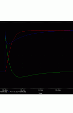
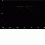
The filters I took for this simulation are both third order with a gradual rolloff. Feedback is done with a summing inverter with an open-loop gain of 100. In real-life one has to be aware of OP-AMP phase-shift of course when doing such things.
This is the FR of the bare filters:
This is the FR of the bare filters:
Attachments
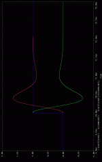
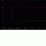
And last but not least the step response. One can see the almost perfect summed response. Comparing this filter to the third-order symmetric subtractive one that I posted before one can see that the heighth of the humps has decreased significantly at the cost of a less steep drop around the crossover frequency. With any type of transient-perfect crossover one has to trade the height of the humps against the steepness of the filters.
Regards
Charles
Regards
Charles
Attachments

Re: Something for the FR guys
What about using transformers for a 'bleed in' of the (-) phase of the HF, to create the LP? That's not the whole story, mind you, but ..just a thought ( A dual wound transformer sandwiched between resistive-active sections for isolation, gain and control of the effectiveness). I dunno. Just throwing it out there.
phase_accurate said:There are always discussions about taking the driver's response into account when designing crossovers.
This can be done with subtractive crossovers as well of course but one has to rely on drivers that are suitable for 6dB filters.
One possible proposal you can see below. The task was to extend a FR driver's response at it's lower end.
The FR driver is high-passed with a first order filter. If it is mounted in a closed box this will amount to a total transfer function of third order (in an open baffle this might be exchanged, i.e. 1st order for the driver and 2nd for the crossover filter).
Another highpass following the actual FR crossover emulates the acoustical behaviour of the driver.
This signal is now subtracted from the input signal, leaving a 1st order lowpassed signal which can be fed to the woofer.
There is no doubt that the woofer has to be usable up to frequencies significantly higher than the crossover frequency (as already mentioned).
Another drawback is the polar response of the arrangement. This can be dealt with by the use of crossover frequencies placed at large wavelengths (compared to the driver sizes, which is quite often the case when FR drivers are used) or d'Appolito configurations (or both !).
It is still not an ideal crossover (which doesn't exist in practice anyway) but it is one possible solution for a transient optimised crossover that takes a driver's response into account.
Regards
Charles
P.S: I also did the maths for symmetrical subtractive crossover and will post it soon.
What about using transformers for a 'bleed in' of the (-) phase of the HF, to create the LP? That's not the whole story, mind you, but ..just a thought ( A dual wound transformer sandwiched between resistive-active sections for isolation, gain and control of the effectiveness). I dunno. Just throwing it out there.
I just like the potential for inherent phase correctness..in a truly passive way. Might sound very special. Something makes me think that this would be the exact result...... a breathtaking clarity. I'm talking about a transformer in the active circuit.
I'm using digital at the moment, just testing the waters initally at the bottom (DCX 2496) price wise..and then trying the pinnacle(sort of) with a highly modified DEQX. Can't say I'm not giving digital a fair chance.
I might go back to passive or analog active, if I could find an actual design of active analog that sounds good enough. I designed a passive crossover function that seemingly alters the phase resposne under load, for normalization, as the phase, FR and levels are altered by the Back EMF. It is a totally passive circuit that corrects this dynamic anomaly, that few take into account or could even consider understanding--actually exists. I have not shared it, as I may issue product some day that uses passive crossovers, why give it to the competition, before the fact? Until then - I keep it to myself. After that, I will willingly share it with the DIY crew. Who knows, they might think I'm an idiot. There are other interesting aspects to it as well. It cannot be patented as it is made up of passive components.
Since I am usng an actual product like the DEQX, I will refrain from making too many commets on it's sonic qualities. Like everything, it does some things spectacularly well. If I can get the clock to work with less jitter (not low enough for me, personally-I'm incredibly sensitive to phase noise), I think I might find it works very well.
FWIW, I found schematics for an analog version of Lipshitz and Vanderkooy's subtracted-delayed XO using allpass networks for the delay. 4th order lowpass and derived 3rd order highpass.
2-way version:
http://users.otenet.gr/~athsam/2way_active_crossover_with_linear_phase.htm
3-way version:
http://users.otenet.gr/~athsam/3way_active_crossover_with_linear_phase_eng.htm
--Dennis
2-way version:
http://users.otenet.gr/~athsam/2way_active_crossover_with_linear_phase.htm
3-way version:
http://users.otenet.gr/~athsam/3way_active_crossover_with_linear_phase_eng.htm
--Dennis
- Home
- Loudspeakers
- Multi-Way
- Active Subtractive XOs