Hi Eric
When I did my simulations (look at the "squarewave" thread) I indeed assumed a 2nd order highpass behaviour of the MSW with quite a high Q.
I think my guess is quite accurate.
When you look at Manger's papers then you will see that the acoustic responses sum between 100 and 200 Hz with the driver's output in phase. So this is quite a good solution SPL- and distortion-wise. But since the MSW behaves like a 3rd order filter together with his 1st order highpass and the woofer's lowpass is of third order as well, the drivers have to be connected out of phase in order to sum correctly.
But it is the method that allows for the flattest amplitude response (wich wouldn't be that perfect with the subtractive XO)possible, with the smallest susceptibility to component tolerances.
The electrical cutoff frequency of the HIGHpass is indeed something above 300 Hz to compensate for the "hump" and the driver's impedance is also catered for with a series resonant network.
I do also expect that a higher order highpass would improve distortion behaviour but at the expense of pulse response (and that's where the Manger excels). Since the MSW is capable of a linear Xmax of +- 3.5 mm I don't give too much attention to this detail, because I don't listen very loud at all.
You made quite clever considerations with your assumption that the hump is detrimental to the application of the subtractive crossover.
I will therefore use a simple EQ network before the MSW's amplifier .
If the whole thing won't work out in practice I will go for an active solution as Manger suggests, but I am quite confident that it should be doable.
Regards
Charles
When I did my simulations (look at the "squarewave" thread) I indeed assumed a 2nd order highpass behaviour of the MSW with quite a high Q.
I think my guess is quite accurate.
When you look at Manger's papers then you will see that the acoustic responses sum between 100 and 200 Hz with the driver's output in phase. So this is quite a good solution SPL- and distortion-wise. But since the MSW behaves like a 3rd order filter together with his 1st order highpass and the woofer's lowpass is of third order as well, the drivers have to be connected out of phase in order to sum correctly.
But it is the method that allows for the flattest amplitude response (wich wouldn't be that perfect with the subtractive XO)possible, with the smallest susceptibility to component tolerances.
The electrical cutoff frequency of the HIGHpass is indeed something above 300 Hz to compensate for the "hump" and the driver's impedance is also catered for with a series resonant network.
I do also expect that a higher order highpass would improve distortion behaviour but at the expense of pulse response (and that's where the Manger excels). Since the MSW is capable of a linear Xmax of +- 3.5 mm I don't give too much attention to this detail, because I don't listen very loud at all.
You made quite clever considerations with your assumption that the hump is detrimental to the application of the subtractive crossover.
I will therefore use a simple EQ network before the MSW's amplifier
.If the whole thing won't work out in practice I will go for an active solution as Manger suggests, but I am quite confident that it should be doable.
Regards
Charles
Daniela Manger says something like this:
The Manger driver is a bending wave transducer at high frequency. When you get into low frequency (in the range of say 150Hz or so?), it becomes a piston driver. Distortion is increased due to the superposition of the bending wave and the piston action.
Petter
The Manger driver is a bending wave transducer at high frequency. When you get into low frequency (in the range of say 150Hz or so?), it becomes a piston driver. Distortion is increased due to the superposition of the bending wave and the piston action.
Petter
>When you look at Manger's papers then you will >see that the acoustic responses sum between 100 >and 200 Hz with the driver's output in phase.
Which paper are you referring to? One of those available on their homepage? Or something they will give you in print?
> But since the MSW behaves like a 3rd order > filter together with his 1st order highpass ...
I am looking at the (presumably free-air) plot in the "MSW-Datenblatt". The response does not look like a second order high pass at all. Would the sealed enclosure be doing this?
>But it is the method that allows for the flattest >amplitude response (wich wouldn't be that perfect >with the subtractive XO)possible, with the >smallest susceptibility to component tolerances.
I am not sure I understand this.
>The electrical cutoff frequency of the HIGHpass >is indeed something above 300 Hz to compensate >for the "hump" and the driver's impedance is also >catered for with a series resonant network.
Only in the passive design, right?
>I will therefore use a simple EQ network before >the MSW's amplifier .
Won't this screw up the phase response?
>If the whole thing won't work out in practice I >will go for an active solution as Manger >suggests,
I know they sell active studio equipment but I've never seen any XO-designs or anything for an active Manger.
Which paper are you referring to? One of those available on their homepage? Or something they will give you in print?
> But since the MSW behaves like a 3rd order > filter together with his 1st order highpass ...
I am looking at the (presumably free-air) plot in the "MSW-Datenblatt". The response does not look like a second order high pass at all. Would the sealed enclosure be doing this?
>But it is the method that allows for the flattest >amplitude response (wich wouldn't be that perfect >with the subtractive XO)possible, with the >smallest susceptibility to component tolerances.
I am not sure I understand this.
>The electrical cutoff frequency of the HIGHpass >is indeed something above 300 Hz to compensate >for the "hump" and the driver's impedance is also >catered for with a series resonant network.
Only in the passive design, right?
>I will therefore use a simple EQ network before >the MSW's amplifier
.Won't this screw up the phase response?
>If the whole thing won't work out in practice I >will go for an active solution as Manger >suggests,
I know they sell active studio equipment but I've never seen any XO-designs or anything for an active Manger.
Hi Eric
I had a look at the response diagrams of my drivers and found an approximation as 2nd order highpass with high Q wouldn't fit too badly. I don't have the phase-response (apart from that in the Manger papers wich also "suggests" a 2nd order response: 90 deg phaseshift at the cutoff frequency) though, which would allow more insight.
At least in the simulations the amplitude response, using the Manger-type crossover, is almost flat. With the XO I'd like to use I didn't get better than +- 2dB (As already mentioned: There's no such thing like a perfect loudspeaker......).
There is a suggestion for an active crossover (being from '92 it uses op-amps that are a bit outdated now but this isn't a problem) from Manger and it's first-order highpass has a -3dB cutoff frequency of 334 Hz.
I have some measurement diagrams from the "Studio Magazin" showing the pulse responses of different studio monitors, also Mangers active MSS. From this pulse response it looks as if they were using the same arrangement, as they suggest for DIY,for their active monitors as well. Also the pulse-response of the famous Medea (first order passive plus built-in electronics for the active feedback controlled woofers) looks alike. I do by no means want to claim that these pulse responses were bad, not even mediocre or good, they are BY FAR BETTER than most speaker's pulse responses !!!!
But I think it should be possible to get it a tick better !!
If you are interested I can fax you the schematic of Manger's original active suggestion.
The answer to the phase question: As long as an amplitude response deviation is caused by an effect whose nature is minimum phase (which I assume it is) then a minimum phase EQ, flattening the amplitude response, will also "straighten out" the phase response.
Regards
Charles
Hi Charles,
you are right, looking at the free air plots it might be something similar to a second order high pass at about 70 Hz.
Wonder how this behaves in a sealed box, i.e. if the frequencies move up.
Tell me when you have figured out a circuit that compensates frequency and phase.
I had been wondering if something similar could be done about the 1.7 kHz hole which seems to really local and should be easier to compensate electrically.
I would love to have the document on the active Manger. I will send you an email with the fax number.
Best regards,
Eric
Thanks Charles,
that looks straightforward enough (370 Hz first order active lowpass, 100 Hz third order low pass made of first order passive + second order active ), and yes, you should be able to do better.
I still believe compensating that little 100-200 Hz bump will be a bear because it is so close to the fundamental resonance.
Eric
Hi all
A little late but maybe still better than never (O.K. that’s not up to me to decide !) my thoughts on the filler driver concept:
The filler driver principle was developed by B&O in order to achieve flat phase and amplitude response (yes they indeed invented cool things too!!!). It is basically an extended two-way system.
It’s original implemetation was using a 2nd order two-way crossover with BOTH DRIVERS WIRED IN PHASE, both filters having the same cutoff frequency.
As already known, this would result in an amplitude response notch at the crossover frequency. The trick is to complement this summed response by the use of a narrow 2nd order bandpass followed by a midrange driver.
This driver is used at full level only over a narrow band but the fil-ter slopes are both of first order only.
The result of this is a system whose amplitude and phase response is flat (i.e. transient perfect or PHASE ACCURATE). The active version is shown on the first diagram.
The advantage of this idea is that it can be implemented passively and actively. There is quite a lot of info on John Kreskovky’s homepage about this. His crossover software also supports the calculation of filler-driver crossovers.
A book issued by Elektor (G. Schwamkrug, R. Roemer: Lautsprecher – Dichtung und Wahrheit, ISBN 3-921608-45-7, page 130) describes the possibility to add the filler driver signal from an active filler-driver crossover to either the woofer or the tweeter channel (shown on the 2nd diagram for the woofer variant). Now the crossover path with the filler driver channel added has been changed to a 1st order slope with a hump. The amplitude response of such a crossover looks in fact like that of the old-fashioned asymmetric subtractive crossover but with the additional advantage of needing more op-amps and capacitors and therefore generating more cashflow, noise and THD.
After some studying I came to the following conclusion: The subtractive crossover can be regarded as an analog computer, computing the complementary signal that is needed to be added to an either lowpass- or highpass- filtered version of the input signal, to reconstruct the original input signal.
So I assumed that it should be possible to generate the filler-driver signal by the use of such a subtractive process and came to the topology shown on the third diagram (=advanced filler driver ! O.K. this sounds a little like hype but I wanted to give it a name):
Again a filler driver crossover, but using only two 2nd order filters as frequency dependent networks. The output signal of the subtracting network will always complement the summed output signals of the highpass and the lowpass that the total sum of responses is flat in amplitude and phase, regardless of capacitor tolerances etc !
It even works for almost any overlap or underlap situation. The only thing that has to be accurate is the gain of the building blocks. This can be achieved with reasonable effort using 1% resistors and op-amps (sorry for using this word again !).
Since there exist no perfect things in the real world, I must also mention a disadvantage of this one over the classic filler driver topology: the driver-dependent frequency response deviations can be better (I deliberately didn’t say easier !) taken care of with three independent filter networks.
I like the idea of having good transient response, but I don’t like the idea of having three drivers and not getting from it what it’s main advantage over two-way systems is: improved IMD figures and/or greater SPL capability.
So I did some more thinking and came to the following conclusions:
The "advanced filler driver" crossover would best be used with a full-range driver that has to be supported at it’s lower and upper end (by moving the highpass cutoff frequency higher and moving the lowpass cutoff frequency lower). There will be two humps in the amplitude response of the derived output, it’s slopes will be of 1st order.
If only two ways are asked for then the circuit can be used as follows: Both cutoff frequencies are the same and the derived channel is split in two by the use of a 1st order lowpass and a 1st order highpass (which is by itself again a transient perfect crossover !) and their outputs summed to the respective branches of the crossover (see 4th diagram).
If all cutoff frequencies involved are the same and all stages have a gain of 1 then the output responses will look like the ones from the symmetrical subtractive crossover (i.e. cascaded subtractive crossover).
But with the possibility to play with the 1st order crossover frequency we can change the distribution of the humps (maybe give a little more of it to the woofer and a little less to the tweeter).
If one goes a step further and plays a little more with ALL the cutoff frequencies and gain of the stages (AFTER the subtracting stage !) involved, he might even be able to take the driver’s responses into consideration when trying to achieve a flat total response.
As with the cascaded subtractive crossovers it is possible to implement crossovers of greater than 2nd order, having flat amplitude and phase response, using this topology. But they would also have the same disadvantages: Large humps (approx 6 dB for 4th order!) and wide overlap area.
Regards
Charles
Attachments
Hi all
Below you will find some simulation results of an "advanced filler driver" crossover.
The LPF pole frequency is 400 Hz and the HPF pole frequency 4 kHZ, both 2nd order with a Q of 0.5.
There are the following items on display:
- amplitude response linear
- amplitude response log
- phase response
- rectangular response
The colours used are the following:
LPF output: green
dreived filler driver: red
HPF output: blue
summed response  : yellow
Have fun !!
Charles
Below you will find some simulation results of an "advanced filler driver" crossover.
The LPF pole frequency is 400 Hz and the HPF pole frequency 4 kHZ, both 2nd order with a Q of 0.5.
There are the following items on display:
- amplitude response linear
- amplitude response log
- phase response
- rectangular response
The colours used are the following:
LPF output: green
dreived filler driver: red
HPF output: blue
summed response
: yellowHave fun !!
Charles
Attachments
This struck me as strange when I first read it. In the meantime, I have gone through Nelson's article and he very clearly states that the derived branch has a first order response.phase_accurate said:
3.) “Classic” subtractive crossovers (active)
These are the ones discussed at the beginning of the thread
A: Simple construction, high immunity to capacitor tolerances
D: same as with 2.) but additionally the disadvantage of one branch only having a slope of 6dB/octave
I must admit I haven't done the math, but intuitively this seems wrong to me. If you have a spectrally flat response and feed it through a second order low pass, wouldn't the difference between the original and the filtered signal automatically have second order high pass characteristic? What am I overlooking here?
Puzzled,
Eric
Hi Eric
Just for curiostity I tried it with a 2nd order lowpass version:
Given is a function (our new highpas H(hp) ) that is derived by subtracting a lowpass transfer-function from unity:
H(hp) = 1 – 1 / (S^2 + S/Q +1) with S = j ( fin/fpole)
We can rearrange that to:
H(hp) = ( S^2 + S/Q + 1 – 1) / (S^2 + S/Q +1)
after some more rearranging:
H(hp) = ( S*Q + 1) / (S*Q + Q/S + 1)
Which is definitely a first order highpass (though of strange form due to the hump).
Q.E.D.
Charles
Hi all
I couldn't resist and simulated afour way subtractive crossover. It is consisting of a tweeter crossover (2nd order highpass 1st order lowpass) followed by a "filler driver crossover" similar to the one from my last simulation.
tweeter HPF pole frequency : 3.4 kHz
mid-high pole frequency : 480 Hz
woofer pole frequency : 250 Hz
again all with a Q of 0.5
There are the following items on display:
- amplitude response linear
- amplitude response log
- phase response
- rectangular response
The colours used are the following:
woofer output: green
low mid (derived) : red
mid-high : blue
tweeter : yellow
summed response : purple
Again the amplitudes sum flat and the rectangular sums to a perfect rectangular again !!
Have fun !!
Charles
Attachments
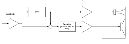
Subtractive x-over for horn/direct radiator hybrid
Here I have something that crossed my mind.
It is primarly intended for the use with direct radiator woofers and horn tweeters.
As with all subtractive crossovers it can be made transient perfect but it would have a wider overlap area than an LR4 for instance. Also the vertical polar response will most probably be worse than what an LR4 could offer. But as we all know: The perfect loudspeaker hasn't been built yet (and most probably never will !! ).
The usual way to delay the woofer against the tweeter (because of the inherent mechanical offset) is the use of allpass filters.
One disadvantage of a subtractive crossover with derived lowpass is the low order of the latter.
By using a Bessel lowpass as delay network this one can be cured to some extent.
I am of course aware that the actual acoustic center of a driver (specially the woofer in our case) is frequency dependant but you can't always get what you want.
There are other solutions that would give a more uniform frequency response and better vertical polar pattern but they will most probably not be transient perfect and they are also more complicated (see John Meyer's patent).
I have not tried it yet but I most probably will, because I have two pairs of speakers of this type, running with crappy passive crossovers, that are awaiting activation. But this will take some time since I am still experimenting with my MSWs. But I didn't want to keep this one secret because someone else might feel the urge to try it out
Regards
Charles
Here I have something that crossed my mind.
It is primarly intended for the use with direct radiator woofers and horn tweeters.
As with all subtractive crossovers it can be made transient perfect but it would have a wider overlap area than an LR4 for instance. Also the vertical polar response will most probably be worse than what an LR4 could offer. But as we all know: The perfect loudspeaker hasn't been built yet (and most probably never will !!
).The usual way to delay the woofer against the tweeter (because of the inherent mechanical offset) is the use of allpass filters.
One disadvantage of a subtractive crossover with derived lowpass is the low order of the latter.
By using a Bessel lowpass as delay network this one can be cured to some extent.
I am of course aware that the actual acoustic center of a driver (specially the woofer in our case) is frequency dependant but you can't always get what you want.
There are other solutions that would give a more uniform frequency response and better vertical polar pattern but they will most probably not be transient perfect and they are also more complicated (see John Meyer's patent).
I have not tried it yet but I most probably will, because I have two pairs of speakers of this type, running with crappy passive crossovers, that are awaiting activation. But this will take some time since I am still experimenting with my MSWs. But I didn't want to keep this one secret because someone else might feel the urge to try it out
Regards
Charles
Attachments
order
Hi Charles,
Excuse my creeping in, I just followed with great interest,
BUT are you really sure that this is first order?
Uli

phase_accurate said:
H(hp) = ( S*Q + 1) / (S*Q + Q/S + 1)
Which is definitely a first order highpass
Hi Charles,
Excuse my creeping in, I just followed with great interest,
BUT are you really sure that this is first order?
Uli
Hi Uli
You are right to question this, since I made a stupid mistake:
It should of course be
H(hp) = ( S^2 + S/Q) / (S^2 + S/Q +1)
(because 1 - 1 = 0 )
)
Which in turn is the sum of a first order highpass and a second order bandpass:
H(hp) = S^2/(S^2 + S/Q +1) + (S/Q)/(S^2 + S/Q +1)
This acts as a first order highpass with a hump, i.e. the final rolloff is definitely that of a first order highpass.
Regards
Charles
You are right to question this, since I made a stupid mistake:
It should of course be
H(hp) = ( S^2 + S/Q) / (S^2 + S/Q +1)
(because 1 - 1 = 0
)Which in turn is the sum of a first order highpass and a second order bandpass:
H(hp) = S^2/(S^2 + S/Q +1) + (S/Q)/(S^2 + S/Q +1)
This acts as a first order highpass with a hump, i.e. the final rolloff is definitely that of a first order highpass.
Regards
Charles
Hi Charles,
Thank you to correct this.
Now I understand!
Uli
BTW: another question:
Whats about a state variable filter?
It has a 2nd order HP out, and a 2nd order LP out
and a 1st order BP out.
Isn´t it that when you sum the LP and the BP and the HP
that you get unity? I mean it´s the easiest way to create
one filter with different outputconfigurations and having
a subtractive filter?
Uli
Re: Subtractive x-over for horn/direct radiator hybrid
There is an AES paper on this exact topic, and i believe the Spica TC50 used a similar approach (passive thou)
dave
phase_accurate said:Here I have something that crossed my mind.
It is primarly intended for the use with direct radiator woofers and horn tweeters.
There is an AES paper on this exact topic, and i believe the Spica TC50 used a similar approach (passive thou)
dave
I think I should go to bed now!
It is of course right that we have a first order highpass with a hump. But it is consisting of a SECOND order highpass and a second order bandpass. The latter one is responsible for reducing the order to one.
The term s*Q + 1 that I wrongfully stated before belongs to the lowpass with a hump which is formed by subtracting a highpass from unity (i.e. the sum of a second order lowpass and a second order bandpass).
Regards
Charles
I found an interesting circuit within a National AN:
http://www.national.com/an/AN/AN-346.pdf#page=6
It is a transient-perfect 2-way crossover that is something like a mixture between a universal filter and a subtractive crossover. Its behaviour is the same as the lowermost circuit from my post #29 within this thread.
Its advantage is that it uses only 3 capacitors and at least one opamp less than my proposal would use. Its disadvantage over mine is that the "humps" can't be as easily played around with.
Regards
Charles
- Home
- Loudspeakers
- Multi-Way
- Active Subtractive XOs