Re: I triple dog dare you......
No, your journey is its own reward.
Fred Dieckmann said:Do I win anything besides the inevitable lecture about where I went wrong, Nelson?
No, your journey is its own reward.
Thanks
It is at that ......... Thanks for your excellent manual which is a very good primer on active crossover design. I really wonder if many people realize what a fascinating and well thought out product it is. I see no comment on how far I am from my desitination, but I take it that I am not wondering in circles in the woods. I have some ideas for a different approach to the resistor and capacitor matrix that would use less parts and PCB real estate at the cost of more programing complexity. Parallel combinations of maybe half a dozen resistors and an equal number of capacitors would give even greater tuning selectivity and the possibility of using all unity gain followers for a simpler circuit with no negative feedback op amp (or discrete transistor op amp) sections. It will be interesting to see the final approach that Mr. Rollins takes with his design. I can see why this would be a formable DIY design project and now understand the time required to undertake it.
It is at that ......... Thanks for your excellent manual which is a very good primer on active crossover design. I really wonder if many people realize what a fascinating and well thought out product it is. I see no comment on how far I am from my desitination, but I take it that I am not wondering in circles in the woods. I have some ideas for a different approach to the resistor and capacitor matrix that would use less parts and PCB real estate at the cost of more programing complexity. Parallel combinations of maybe half a dozen resistors and an equal number of capacitors would give even greater tuning selectivity and the possibility of using all unity gain followers for a simpler circuit with no negative feedback op amp (or discrete transistor op amp) sections. It will be interesting to see the final approach that Mr. Rollins takes with his design. I can see why this would be a formable DIY design project and now understand the time required to undertake it.
Who............
(Everyone join in singing..........)
Lives in a sealed enclosure (of Q = 0.5) under the sea??
SpongeBob HexPhred!
Cranky, and ornery, and feisty is he.
SpongeBob HexPhred!
If DIY abuse is something you wish.........
SpongeBob HexPhred!
Then make a post, and wind up on his "list"!
SpongeBob HexPhred!!!!!!
(I can hear him now............"NO MORE PIZZA FOR YOU!!")
Jocko


driving on highroad without licence

Are you sure that your back engineering on Pass XVR1 is correct?
Can you draw schematic of 6db/octave filter for all frequency with those resistor packs and additional resistor R=12.4k? Or, for example, please tell me what are combinations of resistors for 36, 66, and 106 Hz (I suppose that C is 47nF).
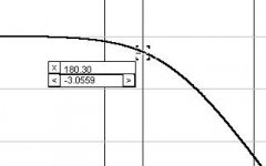
How you get fr=180Hz for R=12k4 and C=47nF?
Isn't f=1/(2*PI*R*C)?
From Dave's site:
It is obvious. In schematic exists only one LPF and this is 6dB/oct. You will easily find in frequency response from 20kHz to 40kHz that curve drops for 6 segments. One segment (unit) is than 1 dB and overall resolution on y-axis is 30dB. (Difference from C and D marker is 4 dB). I expect more from one back engineer.Fred Dieckmann said:I can not tell what your bandpass does with no units for the amplitude (y axis) unless I simulated it.[/B]
Opps..... My "Lancaster" is only 10 years old.This is not a hand holding thread and reading some of the references is required to follow the thread. [/B]
Are you sure that your back engineering on Pass XVR1 is correct?
Can you draw schematic of 6db/octave filter for all frequency with those resistor packs and additional resistor R=12.4k? Or, for example, please tell me what are combinations of resistors for 36, 66, and 106 Hz (I suppose that C is 47nF).
How you get fr=180Hz for R=12k4 and C=47nF?
Isn't f=1/(2*PI*R*C)?
From Dave's site:
Attachments
I guess only Passlabs knows for sure...
quote:
Originally posted by till
High pass should be first or second order at ca. 700Hz.
I want the crossover for the high freqency speaker to provide a 6dB/okt ramp more signal from 10kHz upwards for compensation of the high frequency horns roll of.
I want it to provide about 4dB more between 700Hz or 800Hz and 5,5kHz than beween 5,5 and 10kHz.
Now I am even more confused...
The first section in Till's requirement is for a band pass filter made of a high pass at 700 to 800 hz and a low pass at 5.6Khz.
I assume your band pass is for this range.... your low pass corner(-3dB) is at above 10Khz.
"Are you sure that your back engineering on Pass XVR1 is correct?
The cap is actually 0.047uf for this range and the x1 multiplier.
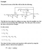
Reasonably...... go look at the graphs on page 39 of the XOVR1 manual. The cap is actually 0.047uf for this range and the x1 multiplier. The circuit's -3dB point moves with the amount of damping. The schematic is shown with the medium Q setting(the op amp with unity gain) selected and with R1=R2 and C1=C2. Run a Spice model and let me know what you get.
I have not looked at the 6dB section yet but image the capacitor value will be different for the same resistor matrix, if it even is the same matrix........
quote:
Originally posted by till
High pass should be first or second order at ca. 700Hz.
I want the crossover for the high freqency speaker to provide a 6dB/okt ramp more signal from 10kHz upwards for compensation of the high frequency horns roll of.
I want it to provide about 4dB more between 700Hz or 800Hz and 5,5kHz than beween 5,5 and 10kHz.
Now I am even more confused...
The first section in Till's requirement is for a band pass filter made of a high pass at 700 to 800 hz and a low pass at 5.6Khz.
I assume your band pass is for this range.... your low pass corner(-3dB) is at above 10Khz.
"Are you sure that your back engineering on Pass XVR1 is correct?
The cap is actually 0.047uf for this range and the x1 multiplier.
Reasonably...... go look at the graphs on page 39 of the XOVR1 manual. The cap is actually 0.047uf for this range and the x1 multiplier. The circuit's -3dB point moves with the amount of damping. The schematic is shown with the medium Q setting(the op amp with unity gain) selected and with R1=R2 and C1=C2. Run a Spice model and let me know what you get.
I have not looked at the 6dB section yet but image the capacitor value will be different for the same resistor matrix, if it even is the same matrix........
Attachments
driving too fast
My manual has only 34 pages. Do you have some special edition?
My attempt in XVR1 reverse engineering (filter only) with some approximation (using standard R and C):
a) fmax/fmin=180/22=8.2
b) for SK filter with R1=R2, C1=C2.....than...... f(i)=1/(2*pi*Ri*Ci)
c) Rmax/Rmin=8.2
d) available resistor raster (using one jumper for setting and with rpacks 4.5k*8 and 18k*4) is 4.5kohm from minimum 4.5k to max 108k (4.5, 9, 13.5, 18, ....103.5, 108)
e) for f1=180 and f2=133 is Rmin/(Rmin+4,5k)=133/180=0,74
f) from d) and e) 4.5/9=0.5, 9/13.5=0.67, 13.5/18=0.75; combination 9/13,5 is used with preresistor for fine tuning, Rpre is 3k9; (9+3k9)/(13.5+3k9)= 0,741
g) from f) Rmin=9+3k9=12.9K, than for fmax=180 C=1/(2*pi*Rmin*fmax)=68.6nF=68nF
h) results (target frequency(Hz)--used resistors(k)--overall resistance--resulting frequency)
180------2*4.5k+3k9------------12.9k------181.5
133------3*4.5k+3k9------------17.4k------134.6
106------18+3k9------------------21.9k-----106.9
88--------18+4.5+3k9------------26.4k------88.7
75--------18+2*4.5+3k9---------30.9k------75.8
66--------18+3*4.5+3k9---------35.4k------66.1
59--------2*18+3k9---------------39.9k-----58.7
53--------2*18+4.5+3k9----------44.4k-----52.7
48--------2*18+2*4.5+3k9-------48.9k-----47.9
36--------3*18+4.5+3k9----------62.4k-----37.5
29--------4*18+4.5+3k9---------80.4k------29.1
25--------4*18+4*4.5+3k9-------93.9k-----24.9
22--------4*18+7*4.5+3k9------107.4k-----21.8
C=68nF, Q=0.707 (another caps for higer frequency are 6n8 and 680pF)
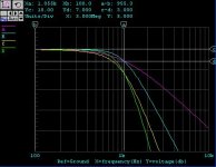
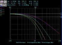
Some curves for 12dB/oct filter outputs (first 8) and switchers position are in pictures below.
Fred Dieckmann said:Reasonably...... go look at the graphs on page 39 of the XOVR1 manual.
My manual has only 34 pages. Do you have some special edition?
My attempt in XVR1 reverse engineering (filter only) with some approximation (using standard R and C):
a) fmax/fmin=180/22=8.2
b) for SK filter with R1=R2, C1=C2.....than...... f(i)=1/(2*pi*Ri*Ci)
c) Rmax/Rmin=8.2
d) available resistor raster (using one jumper for setting and with rpacks 4.5k*8 and 18k*4) is 4.5kohm from minimum 4.5k to max 108k (4.5, 9, 13.5, 18, ....103.5, 108)
e) for f1=180 and f2=133 is Rmin/(Rmin+4,5k)=133/180=0,74
f) from d) and e) 4.5/9=0.5, 9/13.5=0.67, 13.5/18=0.75; combination 9/13,5 is used with preresistor for fine tuning, Rpre is 3k9; (9+3k9)/(13.5+3k9)= 0,741
g) from f) Rmin=9+3k9=12.9K, than for fmax=180 C=1/(2*pi*Rmin*fmax)=68.6nF=68nF
h) results (target frequency(Hz)--used resistors(k)--overall resistance--resulting frequency)
180------2*4.5k+3k9------------12.9k------181.5
133------3*4.5k+3k9------------17.4k------134.6
106------18+3k9------------------21.9k-----106.9
88--------18+4.5+3k9------------26.4k------88.7
75--------18+2*4.5+3k9---------30.9k------75.8
66--------18+3*4.5+3k9---------35.4k------66.1
59--------2*18+3k9---------------39.9k-----58.7
53--------2*18+4.5+3k9----------44.4k-----52.7
48--------2*18+2*4.5+3k9-------48.9k-----47.9
36--------3*18+4.5+3k9----------62.4k-----37.5
29--------4*18+4.5+3k9---------80.4k------29.1
25--------4*18+4*4.5+3k9-------93.9k-----24.9
22--------4*18+7*4.5+3k9------107.4k-----21.8
C=68nF, Q=0.707 (another caps for higer frequency are 6n8 and 680pF)
Some curves for 12dB/oct filter outputs (first 8) and switchers position are in pictures below.
Attachments
Right answer wrong problem?
Your resistor matrix looks a better than mine and I think it would work great for the first order section but still don't see how it works with the second order Sallen Key filter. Page 34 of the manual shows three curves for the 1060 Hz crossover configurations. The high Q is 0 dB down at 1060Hz with about 1.5dB of peaking, the medium Q is -3 db down at 1060 Hz with no peaking ( I believe this is a Butterworth alignment), the low Q setting is 6dB down at 1060 Hz. Page 29 of the manual shows a gain of unity, 3dB and 6db for these values. I can see that your values will work for the high Qs etting but not the other two.....
My more complicated first order filter matrix:
Attachments
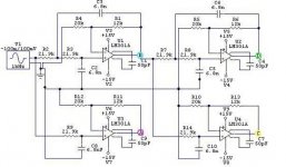
Right answer right problem?
I think that my setup works fine.
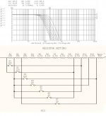
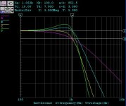
Test shematic below has 4 outputs:
A is 6dB/oct, B is 12dB/oct, C is 18dB/oct and finally D is 24dB/oct.
Q=0,707 for R1, R6,R11 and R13=12k
Q=0,5 for R1, R6,R11 and R13=0.1ohm
Q=1 for R1, R6,R11 and R13=20k.
C=6n8, fr=1060Hz
The resulting diagrams perfectly match the ones published in the XVR1 manual (last page, low pass filters).
Fred Dieckmann said:Your resistor matrix looks a better than mine and I think it would work great for the first order section but still don't see how it works with the second order Sallen Key filter. Page 34 of the manual shows three curves for the 1060 Hz crossover configurations. The high Q is 0 dB down at 1060Hz with about 1.5dB of peaking, the medium Q is -3 db down at 1060 Hz with no peaking ( I believe this is a Butterworth alignment), the low Q setting is 6dB down at 1060 Hz. Page 29 of the manual shows a gain of unity, 3dB and 6db for these values. I can see that your values will work for the high Qs etting but not the other two.....
I think that my setup works fine.
Test shematic below has 4 outputs:
A is 6dB/oct, B is 12dB/oct, C is 18dB/oct and finally D is 24dB/oct.
Q=0,707 for R1, R6,R11 and R13=12k
Q=0,5 for R1, R6,R11 and R13=0.1ohm
Q=1 for R1, R6,R11 and R13=20k.
C=6n8, fr=1060Hz
The resulting diagrams perfectly match the ones published in the XVR1 manual (last page, low pass filters).
Attachments
We have a winner!
I looked at it again after a nights sleep and I believe you are absolutely correct. No more Spice modeling for me at 3 AM! I have shown the jumper connections (I guess I can figure that out at least) for setting the Q. You have now been elected as lead engineer for crossover development. Thanks for your excellent input. You are a sharper guy than I.
Fred
Attachments
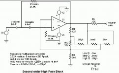
Arrrggg.......
I guess schematic editing should now be added to my list of banned activities for the middle of the night. The R matrix value is 21.9K for 1060Hz as indicated in moamps post #30 in this thread. I am starting to wonder if someone in South Carolina put a curse on me......
I guess schematic editing should now be added to my list of banned activities for the middle of the night. The R matrix value is 21.9K for 1060Hz as indicated in moamps post #30 in this thread. I am starting to wonder if someone in South Carolina put a curse on me......


- Status
- This old topic is closed. If you want to reopen this topic, contact a moderator using the "Report Post" button.
- Home
- Amplifiers
- Solid State
- Active Crossover Activity thread