As we seen to have gone in about 4 directions in active crossover threads. I will start mine and attempt to kept it from being dissected. The purpose of the thread is to start with technical references, CAD, and some simple algebra to allow people the option to go in thier own direction without the constraints of a particular finnished ddesign. Please limit discussions about the Wenever....er I mean the Xenover, to the threads dedicated to that subject. This is not intended to be a whatever floats your boat design thread but focus on classic filter designs as a starting point to progress to the case of active adjustable crossovers. I will focus on Sallen Key type filters for their simplicity and the extensive literature on analysis of this filter.
The inevitable first question is "Why use an active crossover when the classic passive filters like the Butterworth and Linkwitz-Riley are so well documented ?"
Better amplifier speaker interface: The removal of coils and their series resistance gives much better damping factor for the driver. The elimination of complex impedance curve seen by the amplifier by the removal of the passive crossover between the speaker and the amplifier. Simple parallel connected passive networks like zobel networks can still be used for to further making the impedance resistive impedance without the drawbacks of a series crossover. Amps open loop gains often a function of the impedance the speaker and crossover.
Optimization of the amplifier for the frequency range and driver.
Cost: For those capable of building ones own amplifiers and active networks, biamping may be cheaper for the same sound quality that expensive audio grade caps and low ESR inductors would provide. It is MUCH easier to find good sounding inexpensive caps under 0.5uF for the active network than quality caps of several and even tens of microfarads for a passive network.
Tunability: Adjusting levels for drivers of differing efficiencies is easy. Drivers with much different impedances can be used without presenting widely varying load to the amp. Adjusting the crossover for diver offset and mounting angles becomes easier as changes to a speaker design are made. Adjusting the crossover slopes include the driver roll off as part of the filter shape. Many of these tuning methods are possible with a passive network but at much greater cost for components and several orders of magnitude in time required.
Some references that are essential for a good understanding the points outlined above are:
http://www.passlabs.com/pdf/XVR1MAN1.PDF
http://www.linkwitzlab.com/crossovers.htm
Loudspeaker Design Cookbook by Vance Dickason
http://www.amazon.com/exec/obidos/t...f=sr_1_2/103-3454551-3520629?v=glance&s=books
Loudspeaker Recipes: Book 1: Four Two-Way Systems by Vance Dickason
http://www.amazon.com/exec/obidos/tg/detail/-/1882580044/103-3454551-3520629?v=glance
Hi Fred,
As i understand active crossovers in this 4 threads are understood mainly as filters to crossover 2 or more speakers. So they are highpass and lowpass filters. I understand a filter as something you put something in and get less out. One part of the input is subtracted. So there sould be different filter be possible than only high/low passes. Ok, my interest in active xo was the hope for more easy frequency response correction than with simple passive xo. With all those information provided its not that difficult to make a high and lowpass for crossing over some speakers. What i´m missing is information for this:
High pass should be first or second order at ca. 700Hz.
I want the crossover for the high freqency speaker to provide a 6dB/okt ramp more signal from 10kHz upwards for compensation of the high frequency horns roll of.
I want it to provide about 4dB more between 700Hz or 800Hz and 5,5kHz than beween 5,5 and 10kHz.
It should make response like this more linear:
Attachments
Waiting till who knows how long.
Till, yours are good questions and I ask a little patiance as I will try to get the resources you need up in this thread in the next week or two. I will try to give some general advice though......
"I want it to provide about 4dB more between 700Hz or 800Hz and 5,5kHz than beween 5,5 and 10kHz. "
Put a pot in front of the high pass filter section to bring the level down
" I want the crossover for the high freqency speaker to provide a 6dB/okt ramp more signal from 10kHz upwards for compensation of the high frequency horns roll of. "
This is equalization and should be done with a shelf filter wihich could be done with an active filter but it is really not a actually a high pass or low pass filter.
Do you use any Spice programs?
classic filter alignments
There are several types of active filter crossovers. The first thing that differentiates them is whether the filter is a high pass, band pass, or low pass. We will limit the discussion to high pass and low pass. A band pass can be implemented with cascaded high and low pass filters. The second thing that differentiates them the order of the filter. First order Butterworth crossover are 3 dB down at the crossover point and attenuate signals at 6 dB per octave (20 dB per decade). They are minimum phase meaning that the high pass and low pass sum for a signal having the same amplitude and phase as the input signal. Unfortunately the slope is to gradual to use with most speakers. It is very sensitive to driver alignment and driver roll off in the stopband where the response of the filter is rolling off (decreasing in amplitude with frequency change).
Second order filters roll off at 12 dB per octave (40 dB per decade). Each additional order adds another 6 dB per octave (20 dB per decade). The last factor is the filter's Q. The Q of a filter determines the peaking and rate of rolloff at the crossover frequency. The amplitude of the combined driver response at the crossover frequency is greatly influenced by the Q. The Q for cascaded second order filters is the product of the Q for each section. A fourth order Linkwitz-Riley has a total Q of 0.49 and a Q of 0.707 for each of the cascaded second order section.
Further discussion of the standard crossover types will be limited to 1st and 3rd order Butterworth and 2nd and 4th order Linkwitz-Riley filters due to the popularity and good set of parameters for each one. The Butterworth filters are 3 dB down at the crossover frequency and the Linkwitz-Riley are 6 dB down. The Sallen Key circuit will be used due to it's simple topology and well documented and easy tuning.
Many will wonder why one would bother to start with standard filter alignments since an adjustable crossover is usually going to wind up tuned outside one of the classic alignments. Besides providing a good jumping off point further adjustment one can be used to:
Use a known active filter alignment to combine with the driver's roll off to approach a target acoustic filter response.
Emulate a manufacturer's recommended filter type for a particular driver.
Emulate a given passive filter design to replace it with an active crossover network.
References:
“A Practical Method of Designing RC Active Filters,” R. P. SalIen and E. L. Key, IRE Transactions on Circuit Theory, Vol. CT-2, No. 1, pp. 74-85,March 1955.
Active Filter Cookbook by Don Lancaster Newnes; 2nd edition (August 1996) ISBN: 075062986X
http://www.amazon.com/exec/obidos/tg/detail/-/075062986X/102-0845672-1832938?v=glance
Also the last three references in the previous post.
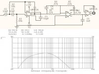
High Frequency Shelf EQ
The op amps could be replaced by followers.
For a tube circuit you may want to multiply the resistors values by 10 and the divide the capacitor value by 10. You just need to drive it with a much lower impedance than the network's and follow it with a much higher impedance. The circuit has 6db of loss at the frequency range much lower than 10KHz and moves to unity gain at very high freqencies.
Attachments

Thank you Fred,
I don´t have spice software, but i see it would be good to learn using it.
The circuit below sorts out the high end roll of of my horn. About the different response in 700<f<5500 and 5500<f<10000: is it possible to make something like a band pass for the lower intervall and parallel it with a padded down high pass 5,5kHz ? Behind this 5,5kHz highpass the correction circuit for the roll of?
Passive and active, line level and speaker level
Hi Fred,
I am not familiar with the threads you mentioned so I don’t know if this is said or not but it might be good to note a few further things.
Just because the filter is made at the line level it doesn’t mean it must be an active filter. Passive filters might be done at line levels as well as at speaker levels. The problem with them is that because of the impedances at the line level the inductors should have an unacceptable high values. Hence we are here, more or less, constraint to the RC filters. However, a passive RC filters, can’t have a high Q. Fortunately, as “we” are now interested for 1st and 3rd order Butterworth and 2nd and 4th order LR, excluding 3rd order Butterworth all these filters might be executed as a passive line level RC filters. Of course, a 6dB filter is always the same, and it is passive by nature.
A passive filter might be a better sounding solution than an active filter.
Pedja
more filter fun
I found a great set of links for active filter design. I have not checked them all out but will report further after looking at some of them more closely
http://www.newwaveinstruments.com/r...ons/active_filter_design_circuit_software.htm
I also recommend the Active Filter Design Techniques SLOA088.pdf at
http://www-s.ti.com/sc/psheets/sloa088/sloa088.pdf
As an introduction to Sallen Key filters:
http://www-k.ext.ti.com/SRVS/CGI-BIN/WEBCGI.EXE/,/?St=99,E=0000000000004113084,K=4990,Sxi=9,Case=obj(26896)
http://www-s.ti.com/sc/psheets/sloa024b/sloa024b.pdf
Also I forgot the picture of Sallen and Key
Attachments
You can download SwitcherCAD from Linear Tech for free.till said:Thank you Fred,
I don´t have spice software, but i see it would be good to learn using it.
http://www.linear.com/new/design_tools.html
http://www.linear.com/software/
I triple dog dare you......
As our fearless leader Mr. Pass said.....
"It certainly is true that the brighter of our readership can reverse engineer an XVR1 from the owner's manual, which is
online at www.passlabs.com
Go ahead, I dare you......."
The attached schematic is pretty much what I believe to be the basic topology of the resistor matrix resistor values and capacitor values for the basic 2nd order filter section. The Q switching appears to be a bit simpler on the passlabs schematic but this was my best shot for now. I cranked up my Spice resolution and think this is real close. The Q's were figured out from the gain specs on page 29 of the manual and the Spice plots compared against the curves on page 34. This was a real pain in the butt to figure out and I can't imagine doing this without a good Spice program and lot of spare time. It was very educational and a good exercise for the Grey Matter to figure out the resistor and capacitor values from the frequency steps and Rpack values in the drawing. The layout of the jumpers with respect to the Rpaks was also a useful clue since the order of the frequency steps appears to minimize trace length to the Rpacks. This is an extremely good PCB layout and I am curious as to the number of layers as I expect it is probably 4 layers.
Do I win anything besides the inevitable lecture about where I went wrong, Nelson?
Attachments
An article on Sallen-Key at my site
http://www.t-linespeakers.org/tech/filters/Sallen-Key.html
and a set of links to active Xo info
http://www.t-linespeakers.org/linx/xolinks.html
dave
http://www.t-linespeakers.org/tech/filters/Sallen-Key.html
and a set of links to active Xo info
http://www.t-linespeakers.org/linx/xolinks.html
dave
till said:High pass should be first or second order at ca. 700Hz.
I want the crossover for the high freqency speaker to provide a 6dB/okt ramp more signal from 10kHz upwards for compensation of the high frequency horns roll of.
I want it to provide about 4dB more between 700Hz or 800Hz and 5,5kHz than beween 5,5 and 10kHz.
Hi,
one idea (simulation only)
Regards
Attachments
Sorry for the omission
Thanks Dave. Maybe we can work on some Mathcad models for some of the standard filter types. I have not used it in years and need to read up.
planet10 said:An article on Sallen-Key at my site
http://www.t-linespeakers.org/tech/filters/Sallen-Key.html
and a set of links to active Xo info
http://www.t-linespeakers.org/linx/xolinks.html
dave
Thanks Dave. Maybe we can work on some Mathcad models for some of the standard filter types. I have not used it in years and need to read up.
Re: I have no idea.....
Talk to me?????
Till says:
"High pass should be first or second order at ca. 700Hz.
I want the crossover for the high freqency speaker to provide a 6dB/okt ramp more signal from 10kHz upwards for compensation of the high frequency horns roll of.
I want it to provide about 4dB more between 700Hz or 800Hz and 5,5kHz than beween 5,5 and 10kHz"
and
"The circuit below sorts out the high end roll of of my horn. About the different response in 700<f<5500 and 5500<f<10000: is it possible to make something like a band pass for the lower intervall and parallel it with a padded down high pass 5,5kHz ? Behind this 5,5kHz highpass the correction circuit for the roll of?"
My circuit is good approximation of desired fr.response in TIll's first post, nothing else. IMO
Fred Dieckmann said:What you have posted is a bandpass filter.
It does not meet the requirements of either the high pass or low pass fillters, which are actually two filters. Back to the drawing board...........
Talk to me?????
Till says:
"High pass should be first or second order at ca. 700Hz.
I want the crossover for the high freqency speaker to provide a 6dB/okt ramp more signal from 10kHz upwards for compensation of the high frequency horns roll of.
I want it to provide about 4dB more between 700Hz or 800Hz and 5,5kHz than beween 5,5 and 10kHz"
and
"The circuit below sorts out the high end roll of of my horn. About the different response in 700<f<5500 and 5500<f<10000: is it possible to make something like a band pass for the lower intervall and parallel it with a padded down high pass 5,5kHz ? Behind this 5,5kHz highpass the correction circuit for the roll of?"
My circuit is good approximation of desired fr.response in TIll's first post, nothing else. IMO
You take the low road and I'll take the high road.....
"a band pass for the lower intervall (700<f<5500) "
"parallel it with a padded down high pass 5,5kHz ? Behind this 5.5kHz highpass the correction circuit for the roll of?"
For the low interval I think you want a high pass at 700Hz followed by a low pass at 5500Hz.
The upper range is a high pass at 5.5KHz followed by EQ for a boost in amplitude for frequencies over 10KHz.
I posted only the shelf EQ. The point off the thread was to investigate adjustable Q and frequency crossovers. I am not going to design specific crossovers for people as it would be immpossible without knowing the driver responses. I can not tell what your bandpass does with no units for the amplitude (y axis) unless I simulated it.
This is not a hand holding thread and reading some of the references is required to follow the thread.
- Status
- This old topic is closed. If you want to reopen this topic, contact a moderator using the "Report Post" button.
- Home
- Amplifiers
- Solid State
- Active Crossover Activity thread