I'll add to that comment. Before attempting to remove any offending particles from the ESL gap, you should completely discharge the speaker. Otherwise, electrostatic force may tend to hold the offending particles where they are. Vacuuming both sides of the panel may also be helpful. Obviously the grill cloth must be removed for this process to work.
But...if you experience the popping only a few minutes after power-up, and then nothing after that, this is normal and requires no further action. The speakers' power consumption is minimal, and they're meant to be left plugged in at all times for optimum listening experience.
But...if you experience the popping only a few minutes after power-up, and then nothing after that, this is normal and requires no further action. The speakers' power consumption is minimal, and they're meant to be left plugged in at all times for optimum listening experience.
How I Saved My Acoustat Model 3s,
Messed Them Up By Saving Them,
And Then Saved Them From Being Messed Up.
aka
Acoustats: Repair of High Voltage Bias (HV) Connection at the Panel
This is a detailed write-up of how I salvaged two of my speaker panels and brought two more panels up to standard. Before this, a panel that loses its HV connection was considered “done”.
This started with one panel that had low sound output and had no high voltage connection. I determined that with an ohmmeter (details in the section on Measuring.) My panel was no good and I couldn't make it worse, so I decided to try a delicate operation that would fix it – if I didn't screw it up permanently.
Ultimately there were poor or open High Voltage Bias (HV) wire connections to four of the six panels of my Acoustat 3 speakers. This work had two benefits: two of the panels which had or developed low volume now played properly. The other two panels improved in dynamics and clarity. All six panels now exhibit the same volume, dynamics, and clarity.
Brandon
P.S. This article took MANY hours - have you ever done technical writing? So did the repairs. So go easy on me. Thanks.
Attachments
Notes about my post above, How I Saved My Acoustat Model 3s:
Now that I know what I'm doing I can fix that problem in an hour or two.
If you have a panel with that problem, study what I've written thoroughly and you will come to know what to do for your situation. It was written with DOING in mind.
Let me know if it helps?
Brandon
Now that I know what I'm doing I can fix that problem in an hour or two.
If you have a panel with that problem, study what I've written thoroughly and you will come to know what to do for your situation. It was written with DOING in mind.
Let me know if it helps?
Brandon
Why is the High Voltage Current-Limiting Resistor so Large?
Discussion: Why is the current-limiting resistor so large in the high-voltage circuit of the MK-121 interfaces?
Why do I care?
If we can safely reduce the resistance by 9/10, to say 25-50 Megohms, the diaphragm would recharge 10-20 times faster, and this may sound significantly better. Is this a legitimate objective?
Yes. See the quote below, published in Stereophile, in a review of the Acoustat Spectra 3 [1].
Some people have done this, though perhaps with a different value of resistance.
But is it safe?
Speculation 1: The 500 Megohm resistor in the high voltage circuit was selected to keep the maximum current flow below that which could cause injury or death to the human body, under all conditions. The most extreme condition would probably be someone who is wet and grounded.
However if you do the math it limits 5,000 volts to to 1/100 of a milliamp. 1 milliamp through the body is just perceptible[2] and is 100 times more than the HV circuit passes so this is far beyond safety.
If we thus increase the available current by ten times it is still 1/10 of perceptible.
Speculation 2: it is to prevent the speaker from arcing, especially diaphragm to stator wire. The speakers are said to not arc even under humid conditions. But arcing is more a function of voltage than current.
Any actual high voltage experts around?
Speculation 3: It is not to prevent arcing, it is to limit damage to the speaker if it does arc.
Speculation 4: It is to limit possible damage at the HV wire to diaphragm connection over the years it will be in charging mode.
Opinions grow on trees. Unfortunately I don’t have enough data to grow a good one.
Research question: What HV currents do other ESLs allow?
If you are in a high humidity area, and you have reduced the HV resistor, could you let us know:
Where (the climate)?
Which interface?
Resistor value?
How long since you did it?
Any negative effects over time?
Sonic benefits?
Brandon
Footnotes:
[1]. The Stereophile quote:
"On many recordings—some Telarcs in particular—at average listening levels of only around 85dB, sudden LF onslaughts (as from bass drum) caused the entire sound to choke down for a moment as though the step-up transformer was saturating. At one point during the Sheffield Shostakovitch 1, three rapid bass-drum strokes took the output level down by increments of about 2dB each, reaching about -6dB before the drum let up and the signal output could recover.
"Acoustat's chief engineer, Jim Strickland, told me this had nothing to do with the step-up transformer, but was due to momentary loss of the high-voltage charge when the diaphragm comes very close to the stator wires. He also pointed out that that is the main reason for incorporating the dynamic woofer."
-- https://www.stereophile.com/content/acoustat-spectra-3-loudspeaker-page-2
Acoustat Spectra 3 loudspeaker
J. Gordon Holt | Nov 9, 2017 | First Published: Aug 1, 1987
[2]. https://www.ncbi.nlm.nih.gov/pmc/articles/PMC2763825/ Re currents through the body.
The purpose of the high-value outfeed resistor in the bias supply is to maintain constant charge operation, not constant voltage. Significantly lowering the value of the resistor will allow the charge level to vary as the diaphragm moves, which causes non-linear distortion. The Acoustat White Paper (and other similar documents from others) explain this better than I can.
In later years, Acoustat remedied the "charge blow-down" effect considerably by increasing the per-square resistance of the conductive coating. This led to less charge migration on the diaphragm, decreasing the likelihood of localized bias blow-down. Dynamic performance was considerably improved with this change. Panels built with the improved coating can be identified by a bias wire that is yellow with a red stripe.
In later years, Acoustat remedied the "charge blow-down" effect considerably by increasing the per-square resistance of the conductive coating. This led to less charge migration on the diaphragm, decreasing the likelihood of localized bias blow-down. Dynamic performance was considerably improved with this change. Panels built with the improved coating can be identified by a bias wire that is yellow with a red stripe.

AcoustatAnswerMan:
Thank you very much for your clarification regarding the high-value outfeed resistor and its purpose.
Would I be correct in assuming that every design aspect Acoustat was accompanied by extensive listening tests? And this included for deciding the value of that resistor?
If so, what I have is as good as it can be.
Brandon
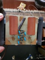
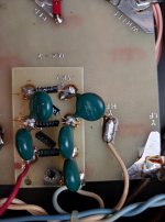
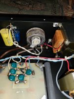
Greetings, I picked up a pair of Model 3's recently and am happy with them . I opened the interfaces (MK-121-2) up to see if the c mod had been done, I still don't know! What I noticed was that even the though the serial numbers were withing half a dozen of each other, their builds were not identical . the differences lie with th the boards with the caps and diodes, The caps are different but same value , the diodes were 25G10 on one interface and 100G10 on the other. The 100G10 one also had the caps and diodes installed on a sister board that matches the original board. Whether or not they left the factory like this I can't tell. I am not savvy enough to know if this is acceptable or not They sound fine both are very close in volume. I am still sorting out their placement.
So advice would be appreciated if this is ok to ru,n with or should I keep the extinguisher close by ! see pics Thanks in advance Dan
So advice would be appreciated if this is ok to ru,n with or should I keep the extinguisher close by ! see pics Thanks in advance Dan
Attachments
Hey Folks, 'Im looking to change the Bias Ladder on a pair of model 3's with the MK-121-2 interface. All schematics steer me to a 25G10 diode. Only problem no matter where I search 25G10 doesn't show up and might be discontinued, I don't know their values . My previous post (above) shows what I have .
Does anyone know the correct diode I should use for this application? Thanks so much.
Does anyone know the correct diode I should use for this application? Thanks so much.
You definitely have two different vintage interfaces. The one with the small PC board holding the bias multiplier is an older version, where the original design had only a 3-stage multiplier, and a higher voltage transformer. These were troublesome, and were upgraded to a 5-stage multiplier and a lower voltage transformer. So it's a good thing you have this upgrade (which was probably done at time of manufacture). If the speakers are playing properly, and at matched volume levels, your bias supply is probably okay. However, these components do age, and replacing them is not a bad idea, especially for older interfaces like yours.
The 25G10 diodes are no longer available. Here's suggestions for suitable replacements for both diodes and capacitors.
Vishay 564R30TSD33 capacitor, 3300 pF, 3000 volts
Mouser p/n 75-564R30TSD33
GP02-40-E3/54 Vishay Semiconductors | Mouser (http://www.mouser.com/ProductDetail...=sGAEpiMZZMtbRapU8LlZD0HbIjlpuZ44XerUncvtHjs=)
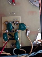
To determine if you have the C-Mod, or not, I would need to see a close up photo of the area around the high frequency balance control, and its associated components.
The 25G10 diodes are no longer available. Here's suggestions for suitable replacements for both diodes and capacitors.
Vishay 564R30TSD33 capacitor, 3300 pF, 3000 volts
Mouser p/n 75-564R30TSD33
GP02-40-E3/54 Vishay Semiconductors | Mouser (http://www.mouser.com/ProductDetail...=sGAEpiMZZMtbRapU8LlZD0HbIjlpuZ44XerUncvtHjs=)
To determine if you have the C-Mod, or not, I would need to see a close up photo of the area around the high frequency balance control, and its associated components.
Thanks so much Andy ! I spent a couple hours spinning wheels trying to get the info you just passed on. The interfaces are 6 apart in serial numbers but I just want everything to be identical . I added pics of the HF balance control area in regards to the C-mod which has not been done.You definitely have two different vintage interfaces. The one with the small PC board holding the bias multiplier is an older version, where the original design had only a 3-stage multiplier, and a higher voltage transformer. These were troublesome, and were upgraded to a 5-stage multiplier and a lower voltage transformer. So it's a good thing you have this upgrade (which was probably done at time of manufacture). If the speakers are playing properly, and at matched volume levels, your bias supply is probably okay. However, these components do age, and replacing them is not a bad idea, especially for older interfaces like yours.
The 25G10 diodes are no longer available. Here's suggestions for suitable replacements for both diodes and capacitors.
Vishay 564R30TSD33 capacitor, 3300 pF, 3000 volts
Mouser p/n 75-564R30TSD33
GP02-40-E3/54 Vishay Semiconductors | Mouser (http://www.mouser.com/ProductDetail/Vishay-Semiconductors/GP02-40-E3-54/?qs=sGAEpiMZZMtbRapU8LlZD0HbIjlpuZ44XerUncvtHjs=)
To determine if you have the C-Mod, or not, I would need to see a close up photo of the area around the high frequency balance control, and its associated components.
Attachments
C-Mod info is here: (#1851)Thanks so much Andy ! I spent a couple hours spinning wheels trying to get the info you just passed on. The interfaces are 6 apart in serial numbers but I just want everything to be identical . I added pics of the HF balance control area in regards to the C-mod which has not been done.
https://www.diyaudio.com/community/threads/acoustat-answer-man-is-here.183168/page-93#post-5225608
Thanks again Andy, I will do the C mod along with the diodes and caps. Some of the components are temporarily Unobtainium. Those diodes had to come from Germany on Ebay. That .01uf 6Kv cap will be an adventure...cheersC-Mod info is here: (#1851)
https://www.diyaudio.com/community/threads/acoustat-answer-man-is-here.183168/page-93#post-5225608
Those .01-uF, 6kV capacitors will be very hard to find. Unless you can find ones with a polypropylene dielectric (used by Acoustat in later production), anything you find will likely be of a lesser audio quality. Also beware of capacitors that will be too large to fit the space available. In this case, if they're not broken, I would leave them alone.
pm sent. I may have what you're looking for.Thanks again Andy, I will do the C mod along with the diodes and caps. Some of the components are temporarily Unobtainium. Those diodes had to come from Germany on Ebay. That .01uf 6Kv cap will be an adventure...cheers
Last edited:
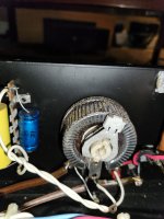
Either Disco-Pete might help you or User Bolserst idea. I did this and so far everything is alright. See attached pic and Post 1579.Thanks again Andy, I will do the C mod along with the diodes and caps. Some of the components are temporarily Unobtainium. Those diodes had to come from Germany on Ebay. That .01uf 6Kv cap will be an adventure...cheers
|Thanks Folks, just what I was looking to do if a single cap couldn't be found. Looks perty yoo!Either Disco-Pete might help you or User Bolserst idea. I did this and so far everything is alright. See attached pic and Post 1579.
View attachment 1098651
Pm me your info.|Thanks Folks, just what I was looking to do if a single cap couldn't be found. Looks perty yoo!
As AcoustatAnswerMan said, if they work, leave them alone. They are probably Polypropylene, I have been told by an expert, and which type do not decay.|Thanks Folks, just what I was looking to do if a single cap couldn't be found. Looks perty yoo!
Brandon
- Home
- Loudspeakers
- Planars & Exotics
- Acoustat Answer Man is here