I'm glad you took the plunge. 3500V measured bias is typical when loaded by a meter. Looking good! 1.9 ohms across the speaker terminals is within range - DC resistance will always be less than AC impedance. Looking good! Attached are some documents you may find useful. When you audition these, be patient - it will take many hours before they really "bloom".
Attachments
Guilford Of Maine is going to be the best choice. Pretty sure whoever made those original covers are long gone. I know the place in Arizona that did the covers, no longer has the fabric. I even think they, (husband and wife) have retired.Ok, this is a VERY long shot. I'm looking for an EXACT replacement for the deteriorating linen on my Monitors. Anyone have a source? View attachment 1085399 View attachment 1085400
https://shop.guilfordofmaine.com/acoustic-fabric/intuition/
https://www.guilfordofmaine.com/acoustic
I just got a pair of acoustat model 3 and the middle panel stopped working. It appears the graphite coating near the wire terminal has worn through. Does anyone know how I can fix it? I was thinking of using this:
MG Chemicals 838AR Carbon Print (Conductive Paint), 12ml (838AR-15ML) https://a.co/d/djLo7iG
MG Chemicals 838AR Carbon Print (Conductive Paint), 12ml (838AR-15ML) https://a.co/d/djLo7iG
Attachments
Last edited:
Thanks for the great info. The speakers I picked up are Spectra 66 model, which I assume is only cosmetically different from the 6600. I found the attached panel diagram but I am confused about which panels are low, mid/low, full range? The diagram does not specify top,bottom,..,inner,middle,outer panels.I'm glad you took the plunge. 3500V measured bias is typical when loaded by a meter. Looking good! 1.9 ohms across the speaker terminals is within range - DC resistance will always be less than AC impedance. Looking good! Attached are some documents you may find useful. When you audition these, be patient - it will take many hours before they really "bloom".
The bass is somewhat weak, but the speaker placement may not be optimal. Still moving furniture to make room for these beasts.
I wonder about this statement in the owners manual: "For the Spectra 6600, no cut in response is available, but the bass response may be boosted by 1, 2, or 3dB. Consult the factory for further details." Is there a bass mod for these? I see references to a web site audiocircuit.com, but cannot access it.
These speakers are mind blowing!
See attached notes from AAMan on adjusting bass EQ for the Spectra models.I wonder about this statement in the owners manual: "For the Spectra 6600, no cut in response is available, but the bass response may be boosted by 1, 2, or 3dB. Consult the factory for further details." Is there a bass mod for these?
Attachments
I just got a pair of acoustat model 3 and the middle panel stopped working. It appears the graphite coating near the wire terminal has worn through. Does anyone know how I can fix it? I was thinking of using this:
MG Chemicals 838AR Carbon Print (Conductive Paint), 12ml (838AR-15ML) https://a.co/d/djLo7iG
Steven,
I doubt the coating actually wore off. I suspect there was oil or something on the panel in that area, before the coating was applied.I have repaired my Model 3’s that had a very similar problem on a few panels.
I found for best sonic results I had to go beyond what you have in mind. My ultimate solution was more drastic but was necessary. I had nothing to lose – the panels were bad -- and a lifetime of fixing things, so I went ahead. There are pitfalls awaiting and while I don’t claim my actual techniques couldn’t be improved upon, I did get outstanding sonic results.
I have been working on a detailed write-up – let me finish it and post it, soon I hope.
Note: What I have done would probably apply to any model.
Brandon
Belated response to the nudge and as AMM said the 44/4400 have panels mounted flat/in the same plane. All the SPECTRAs had the same edge and central support cross sections, I believe, except the 11/1100. The frames details used to be available on audiocircuit but I cannot find them now.NUDGE (re Post 2,825)
If you have a factory framed 2+2 or 4400 with grill cloth off:
What is the exact measurement (front to back) of the vertical center board the panels are mounted to, on the outside edges (left and right sides) of the boards?
It is probably between 3/4" to 2", but I do not have one to measure. Please mention the model.
Pictures of the back, no grill cloth, from different angles, would help too.
Thank you,
Brandon
I have measured a set of Model 2's, 1/2 a 2+2
") , where the 2 panels are angled back at 5 degrees from the front edge of the speakers, for a difference in angle between the adjacent panels of 10 degrees.
, where the 2 panels are angled back at 5 degrees from the front edge of the speakers, for a difference in angle between the adjacent panels of 10 degrees.If you are still after dimensions I can do a measure up of the M2 frame and a Spectra3 that has the central and outer uprights that would be the same as the 44.
Cheers
Grant
Attachments
Grant,
Thank you!
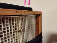
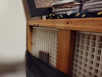
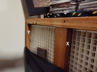
I have managed to mark one of your photos. I need the exact measurements at X and Y, from the grid to the back edge. They look like somewhere between ¾” to 1-1/4”. Measuring to the nearest 1/32” would be nice.
I will be doing a modification project. This info will help enable the write-up to be more universally applicable.
Note: Some things I try, I HOPE will sound better. This one I am SURE will sound better. Bonus: it is inexpensive!
Brandon
Thank you!
I have managed to mark one of your photos. I need the exact measurements at X and Y, from the grid to the back edge. They look like somewhere between ¾” to 1-1/4”. Measuring to the nearest 1/32” would be nice.
I will be doing a modification project. This info will help enable the write-up to be more universally applicable.
Note: Some things I try, I HOPE will sound better. This one I am SURE will sound better. Bonus: it is inexpensive!
Brandon
Attachments
Hi BrandonGrant,
Thank you!
I have managed to mark one of your photos. I need the exact measurements at X and Y, from the grid to the back edge. They look like somewhere between ¾” to 1-1/4”. Measuring to the nearest 1/32” would be nice.
I will be doing a modification project. This info will help enable the write-up to be more universally applicable.
Note: Some things I try, I HOPE will sound better. This one I am SURE will sound better. Bonus: it is inexpensive!
Brandon
I am metric, but confident I have measured better than 0.8mm.😅
X = 37.5mm, 1 15/32"
Y= 18.5mm, 23/32"
I note that "Y" is measured at the outer edge of the panel, but "X" is measured give or take a little bit of parallax, 1" from the inner edge of the panel.
The equivalent 1" measurement at say Y-(1") is 20.5mm, 26/32".
I used the latter to calculate the 5 degrees from the plane of the back edge of the frame.
Hopefully that makes sense.
Cheers
Grant
Grant,Hi Brandon
I am metric, but confident I have measured better than 0.8mm.😅
X = 37.5mm, 1 15/32"
Y= 18.5mm, 23/32"
I note that "Y" is measured at the outer edge of the panel, but "X" is measured give or take a little bit of parallax, 1" from the inner edge of the panel.
The equivalent 1" measurement at say Y-(1") is 20.5mm, 26/32".
I used the latter to calculate the 5 degrees from the plane of the back edge of the frame.
Hopefully that makes sense.
Cheers
Grant
Yes, this is good!
For X, 37.5 mm would be the actual wood thickness?
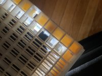
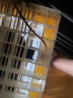
Can you give me a shot of the panel back side, straight on? I want to confirm there is over 1/8" (3 mm) side gap on each panel, outer edges. I know the panels can be shifted slightly, until they hit each other, so close to that is good.
Brandon
Ah no that is the distance from the back of the panel to the rear edge of the outer a. The piece of timber is actually 2" wide and 3/4" thick. It is thicker than this at the centre, between the panels, to achieve the 5 degree angle. There is a strip of thin felt that the grid of the panels are screwed to, so some toleranceGrant,
Yes, this is good!
For X, 37.5 mm would be the actual wood thickness?
Can you give me a shot of the panel back side, straight on? I want to confirm there is over 1/8" (3 mm) side gap on each panel, outer edges. I know the panels can be shifted slightly, until they hit each other, so close to that is good.
Brandon
Hi BrandonGrant,
Yes, this is good!
For X, 37.5 mm would be the actual wood thickness?
Can you give me a shot of the panel back side, straight on? I want to confirm there is over 1/8" (3 mm) side gap on each panel, outer edges. I know the panels can be shifted slightly, until they hit each other, so close to that is good.
Brandon
Replied via pm, I think that should provide the details you asked for.
Look forward to hearing about your mods, in particular about repair of the conductive coating and connection to it.
Cheers
Grant
Grant,Ah no that is the distance from the back of the panel to the rear edge of the outer a. The piece of timber is actually 2" wide and 3/4" thick. It is thicker than this at the centre, between the panels, to achieve the 5 degree angle. There is a strip of thin felt that the grid of the panels are screwed to, so some tolerance
Hi Brandon
Replied via pm, I think that should provide the details you asked for.
Look forward to hearing about your mods, in particular about repair of the conductive coating and connection to it.
Cheers
Grant
Thanks for the PM. (see answer)
I started editing my write-up re repair of the conductive coating, but as it had grown to about 9 pages, it won't be overnight.
It includes what tools, how to determine if you need it, and what sonic benefits I achieved. As well as the procedure.
Brandon
I'm still trying to figure out the best crossover point between my Spectra 11 panels, and my Polk SDA 2B's used as the bass modules.
I could either use a 2nd order circuit operating somewhere below 250 (where?), or a 4th order at 250.
What do you'all think?
I could either use a 2nd order circuit operating somewhere below 250 (where?), or a 4th order at 250.
What do you'all think?
Last edited:
What I think does not matter. I would start at 50 Hz and work up until it overall sounds the best. Try different slopes as you go.I'm still trying to figure out the best crossover point between my Spectra 11 panels, and my Polk SDA 2B's used as the bass modules.
I could either use a 2nd order circuit operating somewhere below 250 (where?), or a 4th order at 250.
What do you'all think?
Brandon
what you are suggesting would cost a fortune. I am hoping to get it right the first time. 170hz is as low as the panel goes before steeply dropping off, but gets progressively weaker below 220hz.What I think does not matter. I would start at 50 Hz and work up until it overall sounds the best. Try different slopes as you go.
Brandon
I need the two units to blend seemlessly without audible overlap.
I was assuming you had an adjustable crossover built in to your electronics. My apologies.what you are suggesting would cost a fortune. I am hoping to get it right the first time. 170hz is as low as the panel goes before steeply dropping off, but gets progressively weaker below 220hz.
I need the two units to blend seemlessly without audible overlap.
You could disconnect all drivers but the woofer in the Polks.
Since the Spectras roll off, second order might work well there.
Find out the Polk woofer crossover setup if you can. Draw it out if you open it up. Playing audio frequency spectrum tones through it would give you some idea if you get stuck (youtube has that).
Good luck.
Brandon
- Home
- Loudspeakers
- Planars & Exotics
- Acoustat Answer Man is here