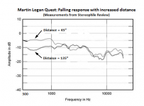
I understand, but no way to cheat the laws of physics…errr…acoustics, that I know of. I ran into this issue with my first ESL hybrid I built which had only a 3ft tall panel. Got it measuring and sounding great at 2m, moved it into the main room where listening distance was 4m and it sounded thin and anemic.I am just concerned about that wicked roll off shown on the graph at my listening distance (-6dB from 1kHz to 250hz).
I recall that years ago Stereophile had measured several of the Martin Logan products at various distances and commented on the issue. Attached is an overlay I had made of the measurements they published for the Quest which used a 45” tall panel. Martin Logan provided a response which at the time I didn’t completely understand, but reading it now I think it provided a good explanation without getting too technical. At the end they basically say that they EQ the speaker for the average listening distance range recommended in the owner’s manual. Interestingly enough, more recent reviews of Martin Logan products have not included measurements at various distances.
Attachments
Interestingly enough, more recent reviews of Martin Logan products have not included measurements at various distances.
Oh, I suspect they don't exist anymore due to this comment
")
"Again, thank you for your revealing work. We look forward to being sliced, diced, and dissected by Stereophile again in the future. "
Question about gluing the stator wires/rods down.... When i put glue on the wires on the eggcrate panel, the glue doesn't go completely "flat". That is, there is a bit of a raised area where the glue is sitting on top of the stator wires. It is fairly thin but you can feel it with your hand when you rub across it.
Is this going to be a problem? Just a little concerned since we are dealing with fairly tight tolerances (e.g. .065 spacing).
Is this going to be a problem? Just a little concerned since we are dealing with fairly tight tolerances (e.g. .065 spacing).
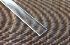
Are you talking about a thin layer of glue encapsulating the wire as shown in pic from Ken Seibert's website: KenSeibert.Com Audio Projects
If so, this is not a problem electrically or response-wise, but does reduce the available excursion by a small amount.
If so, this is not a problem electrically or response-wise, but does reduce the available excursion by a small amount.
Attachments
Yes, in some places on my build, the glue is kinda sitting on top. Not a huge amount but just worried the diaphragm will be banging into it.
I will try to measure the thickness tonight with calipers.
I had the same issue. But I got myself a couple of rolls of 1/4" wide masking tape (hard to find 1/4") and masked off the wires on either side of the glue line.
Then run a bead of over the wires and quickly wiped it flat with my finger and immediately pulled off the masking tape. The tape keeps the excess glue off the adjacent wire surfaces.... works great but a real pain to do.
With my panels being hexagonal sections instead of square, it would be an epic PITA
Hi Bengel,
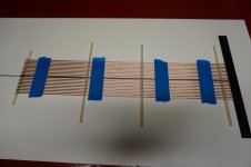
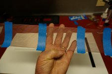
I'm not familiar with the type of ESL you are building or the gluing process(glue on after the rods are placed, or before on the plastic panel). If putting the glue on before would be easier with less mess, you might want to consider pre making stator assemblies and glue them a section at a time. Below is a picture of a small assembly taped together with masking tape. It is just 22 rods across but you can add or decrease the amount. In your case you would substitute the nylon grommets with the bolts you have for separation. It's easier if you have a very flat and smooth board like melamine. Mask the rods about every 7 to 10 inches, making sure the tape does not touch the melamine or it won't slide. Once it's all masked, lift your bolts off and carefully lift or slide the assembly to your panel. If you are careful the masking tape actually keeps the rods very well separated. The other picture is wire assembly in my hand. Don't know whether this is at all helpful for your situation but thought just in case.
Bondsan
Attachments
Hi Bengel,
If putting the glue on before would be easier with less mess, you might want to consider pre making stator assemblies and glue them a section at a time.
Bondsan
I've actually considered this approach. I thought of just clamping the threaded rods to the table and placing the wires "on top" of the rods in the threads/spacers... and build one segment at a time......though I have yet to try it.
In your case I think it is a bit easier as your wires are thicker and you have nice spacer (nice and deep for the wires to sit in).
In my case the wires are "hair like" and you have to be careful with them so they don't get bends in them.
There has to be a better way to do than I am doing it. It is taking forever to get through even 1 panel build.
BTW I am basically following this process....
KenSeibert.Com Audio Projects
As of this moment, I am assembling wire stators with hot glue which I find quite satisfactory uptil now. The glue hardens very quickly making it easy to glue large portions without the concern of messing up previously glued portions. The glue protrudes quite a lot however, which is easily solved by applying a hot iron through baking paper melting the glue perfectly flush with the wires. If you use insulated wires however be sure not to melt the insulation.
Hi bengel
Done some sums on your transformer needs....
I've assumed that you want fL=250 Hz and a bandwidth of 20 kHz. The segmentation and choice of resistor for fL=250 Hz means that the panel behaves as a capacitor of about 82 pF = Cesl in formula below - this is the capacitive load presented by the ESL to the transformer at 20 kHz. I've assumed that the resonant frequency of the loaded transformer =bandwidth (it forms a second-order low pass filter).
Then for:
N = 150, Lamp = 1 uH you need Lt < 110 mH and Ct < 400 pF
N = 150, Lamp = 3 uH, you need Lt < 160 mH and Ct < 195 pF
N = 150, Lamp =10 uH, you need Lt < 195 mH, and Ct < 70 pF
N = 200, Lamp = 1 uH you need Lt < 135 mH and Ct < 280 pF
N = 200, Lamp = 3 uH, you need Lt < 185 mH and Ct < 125 pF
N = 200, Lamp =10 uH, you need Lt <160 mH, and Ct < 32 pF
These are the combined specs for a pair of transformers (one each side of the HT) so each transformer should have half of the given Lt and no more than 2 x the indicated capacitance.
Just heard back from outlaw audio. The output inductance on my amp (each channel) is 1.5 uH.... which I think is a good thing
The output inductance on my amp (each channel) is 1.5 uH.... which I think is a good thing
Excellent ! that makes life much easier.
I have also learned that the Sowter 8986 transformer ELECTROSTATIC LOUDSPEAKER TRANSFORMERS has a leakage inductance of 2.26 mH and an unloaded bandwidth of greater than 100 kHz - that makes the winding capacitance about 1 nF. An example of something very different from what you need.
regards
It is when the beaming concerns a width of only some centimeters, which can easily happen.
Reference? Evidence? Measurements?
At 7 feet, that would be like a fraction of one degree. Seems unlikely.
When you have a "plan view" of a room and sketch a hypothetical pure beam with hypothetical borders drawn in black ink, looks like a terrible hypothetical problem. But when you are sitting in that diffuse beam ("worm's eye view"), it is no problem. Or least, no more of a problem than all the rest of dipole sound propagation.
B.
Last edited:
Just curious what folks think who have made these.... is gluing down the wires every 1/2" overkill? I know you want them stuck down good so they don't vibrate but seems a bit much to me.
Yes. The only reason I did is because the plastic grid had a cross member every 1/2" and I was afraid the wires would rattle against it if I didn't.
- Status
- This old topic is closed. If you want to reopen this topic, contact a moderator using the "Report Post" button.
- Home
- Loudspeakers
- Planars & Exotics
- About to take the ESL plunge