Mine makes a racket under heavy load too. Try playing big woofer kick drums, the SMPS clicks with each beat. I think it is piezoelectric effect on ceramic caps, and magnetorestriction on the transformer plates. They mechanically move under high voltage or current.
This pretty much comes from the transformer. (Same for "weeping" output filter inductors)
I also had supected the MLCC on the TPA3251D2 board to make noise, but haven't investigated any further.
While the output inductors some kind of weep, "clicking" could occur on inductor saturation. More capacitance wouldn't help usually.
D
Deleted member 148505
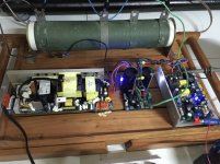
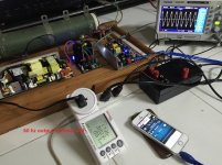
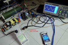
I rushed in to setup my amp with this SMPS to save myself from embarrasment 
As I have suspected, running at 20hz makes the rail voltage go as high as +/-58V DC before the protection kicks in.
So I've put 10000uf per rail and the amp was able to output 20hz.
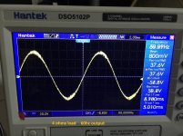
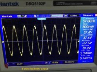
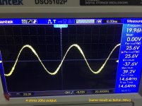
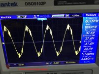
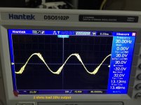
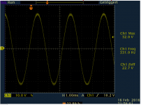
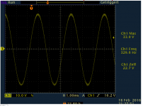
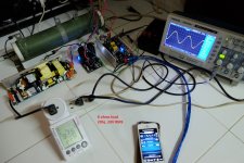
Weird thing is that the waveforms are not clean at high power when the amp outputs 20hz. At 8 ohms and 4 ohms, cleanest output that I can get with 20hz was only 25.6V RMS. At 2 ohms load, only 20V RMS (see attached pics). With a linear supply, I can get cleaner waveforms with 20hz at higher power output.
Good thing about this amp is the regulation, unlike linear supplies, rail voltage does not sag.
Attached pics for data.
As I have suspected, running at 20hz makes the rail voltage go as high as +/-58V DC before the protection kicks in.
So I've put 10000uf per rail and the amp was able to output 20hz.
Weird thing is that the waveforms are not clean at high power when the amp outputs 20hz. At 8 ohms and 4 ohms, cleanest output that I can get with 20hz was only 25.6V RMS. At 2 ohms load, only 20V RMS (see attached pics). With a linear supply, I can get cleaner waveforms with 20hz at higher power output.
Good thing about this amp is the regulation, unlike linear supplies, rail voltage does not sag.
Attached pics for data.
Attachments
-
 IMG_4262.jpg814.4 KB · Views: 330
 -
 4ohm-60hz-2.JPG339.8 KB · Views: 95
 -
 4ohm-60hz-1.JPG341.5 KB · Views: 88
 -
 4ohm-20hz-1.JPG352.3 KB · Views: 97
 -
 8ohm-60hz-2.JPG381.1 KB · Views: 307
 -
 8ohm-60hz-1.JPG365.2 KB · Views: 313
 -
 8ohm-4ohm-20hz-2.JPG343.7 KB · Views: 312
 -
 8ohm-20hz-1.JPG348.2 KB · Views: 321
D
Deleted member 148505
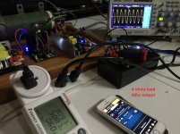
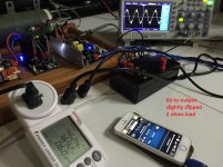
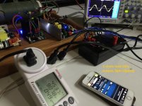
Total system idle power consumption is around 20W (JLA-250 module idle is around 5W)
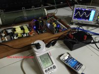
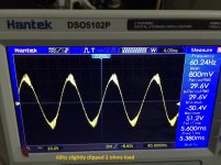
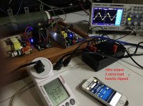
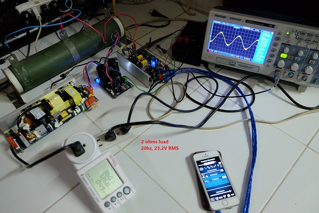
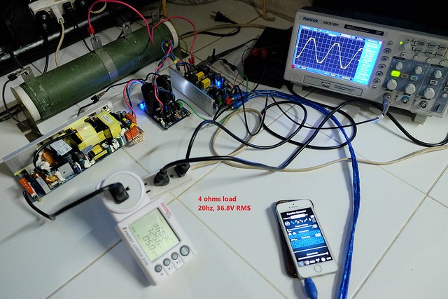
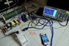
More data at 2 ohms load. See attached pics
Overcurrent protect kicks in when energy logger shows 800W.
I used my module JLA-250D V1.2 +/-85V Max voltage, uses IRFB5620, VER2923-223 inductor.
More data at 2 ohms load. See attached pics
Overcurrent protect kicks in when energy logger shows 800W.
I used my module JLA-250D V1.2 +/-85V Max voltage, uses IRFB5620, VER2923-223 inductor.
Attachments

@jlester:
What in your opinion is the source of the higher frequency noise/junk superimposed on top of the waveform? Do you think that this is the power supply going into distress, or does it have something to do with the amplifier? How about the reaction of the power supply to the large capacitor on the output? I thought that was not a good idea in general for an SMPS...
Could you try changing this to a low pass filter by adding a small value power resistor, e.g. 0.22R, 25W+ in between the PS and your cap bank? This would give a first order low pass with corner frequency at 72Hz that might remove the junk if it is coming from the PS. Note, when drawing current the power dissipated in the 0.22R series resistor would be:
power (VA) / current / resistor power dissipation
100VA / 1.88A / 0.8W
500VA / 9.4A / 19.6W
1000VA / 18.9A / 78W!
Not sure how you are getting the PS to output 1000VA... Apologies if my numbers are off, but you get the idea.
D
Deleted member 148505
@jlester:
What in your opinion is the source of the higher frequency noise/junk superimposed on top of the waveform? Do you think that this is the power supply going into distress, or does it have something to do with the amplifier? How about the reaction of the power supply to the large capacitor on the output? I thought that was not a good idea in general for an SMPS...
Could you try changing this to a low pass filter by adding a small value power resistor, e.g. 0.22R, 25W+ in between the PS and your cap bank? This would give a first order low pass with corner frequency at 72Hz that might remove the junk if it is coming from the PS. Note, when drawing current the power dissipated in the 0.22R series resistor would be:
power (VA) / current / resistor power dissipation
100VA / 1.88A / 0.8W
500VA / 9.4A / 19.6W
1000VA / 18.9A / 78W!
Not sure how you are getting the PS to output 1000VA... Apologies if my numbers are off, but you get the idea.
I captured those waveforms at the onset of clipping, with 3V to 4V RMS lower, the waveform is clean. Though the residual of class-d is cleaner when I am using a linear supply. When I use this supply, there is a slight blip on the 480mV residual.
With the addition of 10000uf caps, at power on, the SMPS emits hiiissssst sound for about half of a second, then the LEDs of cap supply module is slowly glowing. In comparison, when I am using a transformer + rectifier, the LEDs will instantly glow.
Last edited by a moderator:
I captured those waveforms at the onset of clipping, with 3V to 4V RMS lower, the waveform is clean. Though the residual of class-d is cleaner when I am using a linear supply. When I use this supply, there is a slight blip on the 480mV residual.
With the addition of 10000uf caps, at power on, the SMPS emits hiiissssst sound for about half of a second, then the LEDs of cap supply module is slowly glowing. In comparison, when I am using a transformer + rectifier, the LEDs will instantly glow.
OK, I see. I somehow got the idea that the waveforms you showed were indicative of all output powers. Thanks for clarifying that this behavior is only found at or near clipping.
I'm sure the SMPS is not happy turning on to a near dead short (the discharged cap bank)!
Weird thing is that the waveforms are not clean at high power when the amp outputs 20hz
You pretty much hitting the smps inductors current vs. inductance. Would guess it's saturating at charging the 10mF cap + suppliing your amp. This does alot of stress to your secondary rectifiers, i wouldn't do that. The 10mF wouldn't help on 20Hz either to keep the rails stiff, it just dampens out subharmonic oscillation of your supply - so you'd better change the compensation at the control loop.
Have you scoped the voltage at the rectifiers and fets with/out the big cap?
Would guess it's saturating at charging the 10mF cap + suppliing your amp.
Why would it be charging the caps while powering the amp unless he is booting up with the signal live? Once they are charged up, they should just be compensating for any voltage sag in the lines during high load spikes.
I agree that for constant frequency output like this it will not do a whole lot, maybe just help out a bit at the top of the sinusoid. Big storage caps can be very helpful for music and movies with a lot of LFE stuff if the supply is a bit under rated though. Probably useful to put a bit of resistance between the SMPS and the cap bank just to create an artificial voltage sag.
Because dI/dT increases with increased capacitance at fixed frequency.Why would it be charging the caps while powering the amp unless he is booting up with the signal live
This is from my LLC supply, connected to an amp at 235Wrms combined into 5R and 6000uF bulk capacitance at 330Hz. This plot shows the voltage at the resonance-capacitor. The high current peaks are due to the high secondary capacitance.
This is same with only 100uF Polymer at same levels:
Same performance, less stress for the switches + rectifiers.
Output performance with 6000uF:
And 100uF:
Any different?
So if you want to increase capacitance, do it on primary side for Q=C*U reasons.
(Measurements and plots taken by @voltwide )
Well, short math:Once they are charged up, they should just be compensating for any voltage sag in the lines during high load spikes.
If your bulk cap is having an ESR of 100mOhms, at 0-10A current peak, the rail is modulated by 100mR*10A = 1Vpp, theres nothing you can do about except lowering the ESR. Now if you want to support the rails for i.e. 10ms there is
R*C = 10ms with R=100mR -> 10ms/100mR = 0.1Farads or 100,000uF. So what if you pump out 20Hz continiously? The caps are always "empty", so they get recharged all the time. As the primary side of the SMPS is only recharged at 100/120Hz, there's this high current demands you see on the scope plot. -> Better, more capacitance on the primary side.
Having 10000uF at 36V is C*U = 0.01F * 36V = 0.36As, while 1000uF at 380V = 0.001F * 380V = 0.38As
Increasing this 1000uF on primary side to i.e. 4700uF gives: 1.786As which transforms to secondary as: 1.786As/36V = ~50000uF
Attachments
-
 tpa3152_clipping_5R_pin_235W_c_sec_6000uf_ch1_c_res.png40.9 KB · Views: 433
 -
 tpa3152_clipping_5r_pin_235W_c_sec_100uF_ch1_c_res.png63.2 KB · Views: 450
 -
 tpa3152_clipping_5r_pin_235W_c_sec_100uF_ch1_left_out.png17 KB · Views: 432
 -
 tpa3152_clipping_5R_pin_235W_c_sec_6000uf_ch1_left_out.png17.6 KB · Views: 422
Last edited:
doctormord:
Like I said, I don't think it will help performance except for a few specific cases, but I don't see anything on those plots to indicate that there would be more stress to the switches or rectifiers.
It would seem to be in the highest voltages for longer with lower capacitance, as expected, and in the middle region for longer with higher capacitance, also as expected.
The main reason to increase capacitance on secondary vs primary, is that you have other losses between the two (ex. transformers, switches, diodes), which will all affect the response time to a current demand on the secondary side depending on the switch mode controller you are using. You are correct though, that ESR is very important to consider here. I am quite used to using parallel banks or ceramics, or specific low ESR electrolytic or even tantalum at the lower voltages,which negates most of that concern, so do excuse my ignorance
Last edited:
It would seem to be in the highest voltages for longer with lower capacitance, as expected, and in the middle region for longer with higher capacitance, also as expected.
The plots show exactly the opposite. The 6000uF plots have high peaks synced to the mains frequency, where the low (100uF) is more of a steady current stream. So, to my knowledge, and others, average current flow is less stress to the parts than high surge currents like for higher capacitance.
Maybe you haven't seen the calculations? Even 10000uF secondary does nothing to the rail support at 20Hz, it's just to less energy stored in the caps.
With 100mR and 10mF there's only 1ms until rail sag is dominated by ESR of the caps.
No problem with your ignorance, if things work for you - fine. different approach, different results.
Of course, for the primary approach, you'll have to make sure, that the secondary bulk capacitance can "bridge" the loop reaction time of your controller. But this also can be calculated if frequency is known. 20Hz is way below the reaction time of almost all SMPS implementations, so primary approach wins.
Edit:
Tantalum - never used, never will.
Last edited:
D
Deleted member 148505
The problem with this abletec supply is that it's not capable of sinking current from the half bridge class-d.
When I tried to output 20hz from the amp, without the secondary capacitors to absorb the current, the supply voltage was being pumped up which is why the abletec goes to overvoltage protection.
Bus pumping is being aggravated when the class-d amp has higher current and lower frequency output. In case with this SMPS + jlamp combo, bus pumping can be observed at 120hz and below.
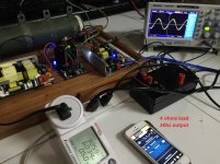
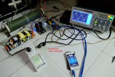
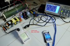
I rewired the setup such that the ground of resistive dummy load is on the capacitor bank, as pointed out by troystg. Also, my probes were not properly compensated yesterday hence the location of clipping in the previous shots is not on the peaks of the sine wave. Waveforms at 20hz went normal much like when I measured it 60hz or 1khz.
I think this SMPS is only good for 4 ohms 250w subwoofer. Personally, I'll use this on my GB150D module.
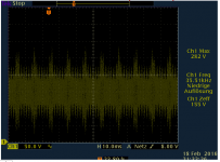
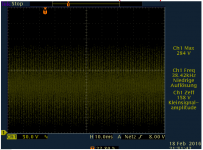
2 ohms near clipping
8 ohms hard clipping

4 ohms hard clipping
When I tried to output 20hz from the amp, without the secondary capacitors to absorb the current, the supply voltage was being pumped up which is why the abletec goes to overvoltage protection.
Bus pumping is being aggravated when the class-d amp has higher current and lower frequency output. In case with this SMPS + jlamp combo, bus pumping can be observed at 120hz and below.
I rewired the setup such that the ground of resistive dummy load is on the capacitor bank, as pointed out by troystg. Also, my probes were not properly compensated yesterday hence the location of clipping in the previous shots is not on the peaks of the sine wave. Waveforms at 20hz went normal much like when I measured it 60hz or 1khz.
I think this SMPS is only good for 4 ohms 250w subwoofer. Personally, I'll use this on my GB150D module.
2 ohms near clipping
8 ohms hard clipping
4 ohms hard clipping
Attachments
D
Deleted member 148505
Jlester,
Very nice work - thanks for taking a careful look at this supply. Knowing it can support a 250w amp is good info to have. Is a capacitor bank necessary for operation to 250w with an IRS2092 in general or it depends on the particular amp?
For mono half bridge class-d used for full range and subwoofer applications, additional secondary capacitors will be beneficial. Since this abletec smps is (probably) not a 2-quadrant capable power supply, additional caps will absorb the power coming back from the irs2092 half bridge amp. 4700uf to 10mF will do, adding CLC/CRC implementation is better. Softstart is mandatory to slowly charge the caps at start-up.
For bridged, inverted in/out setup, or for amp used in mid/highs it is not needed.
Clicking at 20hz is inaudible in my setup.
PS: I managed to destroy the fuse on the negative rail in my 2 ohms, 20hz full clipping test. Good thing the amp and smps both survived.
I think this SMPS is only good for 4 ohms 250w subwoofer. Personally, I'll use this on my GB150D module.
I see this a little differently.
At 8 ohms clipping can clearly be seen on the scope (picture labeled with 8 Ohms, 36.8Vrms). At this RMS output voltage the peak voltage is 1.41 times higher, or over 51V (assuming sine wave with non-clipped peaks). But the SMPS rails are only 53V and your output devices have a few volts drop in them, so you are running out of VOLTAGE in this case, and not POWER (or current) from the SMPS. The V^2R power into 8R at 36.8Vrms is only 170W - this means you could connect several more amps like this to the SMPS before you use up the available current capability. I'm thinking of general full range audio, not low frequency specific use.
Likewise, for the pic showing 4R load at clipping at the same output voltage the amp has reached its maximum output for these rail voltages. V^2R is now about 340W. I don't see why you could not connect additional amplifier modules since (at least on paper) the SMPS can supply 450W and more for brief peaks.
As an example that I have mentioned before, I have three 2092 based class-D amps (one IRAUDAMP7 and one L15D) running off of a single AbleTec PS and I have experienced zero problems - there are two 8R drivers and one 4R driver (4R is the tweeter) reproducing music signals. Sine wave testing is really not all that indicative of performance on music signals except for subwoofer duty only. One doesn't need to do sine wave testing to know how many Watts a single amplifier can produce when powered by this PS before you run out of rail voltage... you have simply measured this behavior.
On the other hand, I strongly agree that bus pumping is a problem with the SMPS for high power (>250W) low frequency signals, but only with Class-D amps. Class AB amps, like your GB150D design, do not pump energy back to the PS. Bus pumping is only encountered with half-bridge class-D amps.
Last edited:
D
Deleted member 148505
Yes couldn't agree more. Music has low crest factor, based on abletec smps specsheet, we can run full output music continuously for whole day.Sine wave testing is really not all that indicative of performance on music signals except for subwoofer duty only. One doesn't need to do sine wave testing to know how many Watts a single amplifier can produce when powered by this PS before you run out of rail voltage... you have simply measured this behavior.
For subwoofer duties I just estimated a compatible driver that can be used with this supply. I was referring to darpmalone's post earlier, because he intended to use my class-d module with this SMPS. Also I've read in a previous post that this amp is "wimpy" when used with IRS2092 based amp to drive a subwoofer. That is also why I measured the behavior on low frequencies.
I purchased this power supply along with the Parts Express Sure IRS2092 2X250w amplifier board.
I have it running and have loaded the secondary supplies with a small fan and the 150R resistor.
The amp performs quite fantastically on my Overnight Sensation mains, with better treble and upper-mid clarity compared to my Pioneer Elite receiver.
However, I purchased and built this for subwoofer duty. I get some very bad static/popping noises when there is low frequency (probably less than 30hz) material being reproduced, even at moderate (-20 on the receiver) volume.
Since I am quite a noob at this, is the static popping the result of bus pumping or just the limits of the supply? It is not the subs bottoming out. If it is the bus pumping, I'd still like to have this for sub duty, and if I add the additional caps would this solve the problem? If so, how exactly would I do that?
thanks
Last edited:
I purchased this power supply along with the Parts Express Sure IRS2092 2X250w amplifier board.
I have it running and have loaded the secondary supplies with a small fan and the 150R resistor.
The amp performs quite fantastically on my Overnight Sensation mains, with better treble and upper-mid clarity compared to my Pioneer Elite receiver.
However, I purchased and built this for subwoofer duty. I get some very bad static/popping noises when there is low frequency (probably less than 30hz) material being reproduced, even at moderate (-20 on the receiver) volume.
Since I am quite a noob at this, is the static popping the result of bus pumping or just the limits of the supply? It is not the subs bottoming out. If it is the bus pumping, I'd still like to have this for sub duty, and if I add the additional caps would this solve the problem? If so, how exactly would I do that?
thanks
What is the Re (or nominal impedance) of the driver used in the sub?
Hi Charlie,
I have two 8 inch subs which (I think) are 4 ohm nominal drivers running one on each channel. If my suspicions are correct, they are JL-Audio 8W0-4 with an Re of 3.3 ohms according to the spec sheet.
My end goal is to get the RSS390-HO to run one of those off of each channel, but don't want to do that until I know I can use this amp to do the 20hz LFE stuff.
- Status
- This old topic is closed. If you want to reopen this topic, contact a moderator using the "Report Post" button.
- Home
- Amplifiers
- Class D
- Abletec 53v Dual Rail 450W Supply for $20