AndrewT said:C32 is too small.
It needs to be >= 22k/680r * sqrt(2) * 4u7F >= 215uF. Use 220uF.
C42 seems a bit big @ 47pF
R = 150 at output also seems big, only 8mA passing Q60 & 51.
Does the mirror load on the LTPs work when you have dual complementary VAS?
The 100 uF(still think that 47u is good) comes from low frequency ~5hz(not audible) => f=1/(2*3.14*R*C) ;= 0.16/(680*C);;;C=0.16/(f*R)=0.16/(680*47u)=5 hz.
C42 is calculated to minimise the noise band > pole at 154khz.(0.16/(22k*f)
Q60 and q51 working at 1mA ! not 8 . 2sc5171/1930 is working at 8-10ma. big input impedance for not oveloading vas => small thd . about the mirror ltp ...look at stochino's amp !
An capacitor + another R to ground will be better ? or do you want to say something else ?roender said:
Catalin,
May I suggest you to not reference CCS's biasing resistors to ground?
Try to make the input stage + VAS as much as possible a constant current compound stage.
Keep the ground as clean as possible and use a separated PSU for output stage, and for inputs stages a good ccs+shunt feedbackless PSU
Regards,
Mihai
Thanks !
Lumba Ogir said:Hi,
I would not make the voltage amplifying section complementary symmetrical.
Can you explain why?
Thank you
Catalin, you are absolutely right about stochinos amp, but look more carefully and youll see why his vas looks the way it does. He was clever and found a way to define the vas current, try define it on your design.
In your case the mirror you hae there will help but i dont think it will overcome the problem completly
In your case the mirror you hae there will help but i dont think it will overcome the problem completly
Here is some info by members with much more theory knowledge than me and some diffrent ways to look at the problem. Theres many more threads I can refer to. The Jlh solution works but it has some flaws too, read the whole thread.
http://www.diyaudio.com/forums/showthread.php?s=&threadid=16796
http://www.diyaudio.com/forums/showthread.php?s=&threadid=16796
Lumba Ogir said:catalin,
for a more favorable distortion pattern. Then I would use the resources to linearize the open-loop.
I think that distortion is less(crossover,pozitive and negative rail have their way,etc,) with complementary design and a lot other advantages .
homemodder said:Here is some info by members with much more theory knowledge than me and some diffrent ways to look at the problem. Theres many more threads I can refer to. The Jlh solution works but it has some flaws too, read the whole thread.
http://www.diyaudio.com/forums/showthread.php?s=&threadid=16796
It' not like his problems.
In that design the current vas don't change with the vcc.just one aspect
Catalin the designs in that thread especially the first 2 are exactly what you have, taking away the cascodes.
You going to play a lot around with values, keep in mind that real transistors have do not match so well compared to simmed ones.
If this type of biasing worked we would have already seen thousands of amps using it, look at the date of that thread 2003, there are threads even earlier than this.
You going to play a lot around with values, keep in mind that real transistors have do not match so well compared to simmed ones.
If this type of biasing worked we would have already seen thousands of amps using it, look at the date of that thread 2003, there are threads even earlier than this.
Lumba Ogir said:catalin,
well in that case... keep it that way.
Lumba, even with the simetrical amp the open loop to 20khz is still 65db
") from the original (200uV) .
from the original (200uV) .
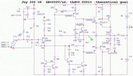
Let's discuss a little abot Current feedback !
Let's discuss a little about current feedback amps .
I obtain with this circuit :
Slew rate 200V/uS . Phase margin > 70 degrees .Thd 0.0001 % .Open loop gain 137 db ; 90db at 20khz !
Bandwith 22mhz without input filter .
What disadvantages ant what advantages it brings ?
I think that the stability is one problem .
What do you think ?
Attachments
very intresting Catalin
if Q88 is 2SA1302 maybe more stable
because in CFP OS --> hFE paramenter is foundamental
between complementary in common collectors
also
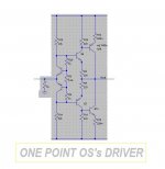
have just one point to drive Output Stage... see figure
can improve stability because front-end have a common load

if Q88 is 2SA1302 maybe more stable
because in CFP OS --> hFE paramenter is foundamental
between complementary in common collectors
also
have just one point to drive Output Stage... see figure
can improve stability because front-end have a common load
Attachments
Attachments
- Status
- This old topic is closed. If you want to reopen this topic, contact a moderator using the "Report Post" button.
- Home
- Amplifiers
- Solid State
- a wonderfull sziklai