Brian,6 inches of absorbent material should be effective all the way down to 100 Hz. It should dramatically reduce the impact of the slot's geometry on the frequency response.
If there is room for 6 inches of absorbent material, the plenum has been made too large
") .
.If the plenum is properly sized, the peaks will be around 180 Hz and above, almost an octave above a sub's usual pass band, and be of little concern with most crossovers, and easily equalized with DSP.
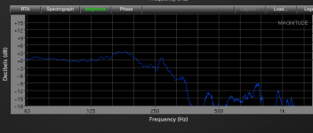
The frequency response chart below is from a 2x15" PPSL with a 7.5" x 15.25" x 15.25" plenum.
Art
Attachments
Is this the same thing?
http://www.diyaudio.com/forums/subwoofers/255959-sim-slbp_pp-maybe-more.html
http://www.diyaudio.com/forums/subwoofers/255959-sim-slbp_pp-maybe-more.html
The PPSL thus far discussed in this thread all have ports separate from the plenum, your picture has the plenum forming the latter part of the port with the end flared, a different "thing", though similar.Is this the same thing?
Using the plenum as part of the port eliminates the cabinet volume "wasted" in the plenum.
The PPSL thus far discussed in this thread all have ports separate from the plenum, your picture has the plenum forming the latter part of the port with the end flared, a different "thing", though similar.
Using the plenum as part of the port eliminates the cabinet volume "wasted" in the plenum.
Art,
Do you think the calculation for the vent/ plenum combo would be the same for vent separate from plenum? Combining them is an interesting idea.
The PPSL thus far discussed in this thread all have ports separate from the plenum, your picture has the plenum forming the latter part of the port with the end flared, a different "thing", though similar.
Using the plenum as part of the port eliminates the cabinet volume "wasted" in the plenum.
However ..... the back wave (radiating into the cabinet) is opposite phase to the "front wave". By having the backwave next to the front wave, won't there be some serious cancellations over a substantial amount of the bandwidth?
However ..... the back wave (radiating into the cabinet) is opposite phase to the "front wave". By having the backwave next to the front wave, won't there be some serious cancellations over a substantial amount of the bandwidth?
I wouldn't think that would be a problem. A 60Hz wavelength is 18.75 feet (or thereabouts) and lower even longer. Phase cancellation as caused by what is passing thru the port should be negligible to nonexistent. However I invite others to offer their thoughts.
The calculation is the same, other than the area taken up by the drivers needs to be accounted for.Art,
Do you think the calculation for the vent/ plenum combo would be the same for vent separate from plenum?
No, the same concept has been used in EAW's SB1000 cabinets for many years, though both cones face the same direction in their cabinets.By having the backwave next to the front wave, won't there be some serious cancellations over a substantial amount of the bandwidth?
Hi Y'all,
It may be obvious, but the connections to one of the drivers need to be inverted from the other one, otherwise cancellation will occur.
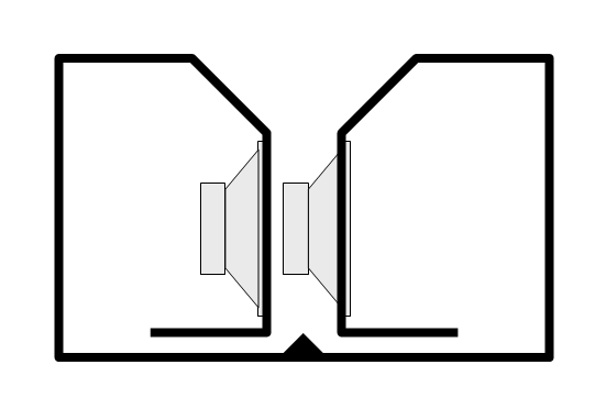
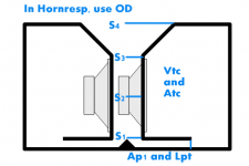
I someone wants to see what this will do, here is the basic layout that can be used in Hornresp for this enclosure:
Regards,
It may be obvious, but the connections to one of the drivers need to be inverted from the other one, otherwise cancellation will occur.
I someone wants to see what this will do, here is the basic layout that can be used in Hornresp for this enclosure:
Regards,
Attachments
Hi Y'all,
It may be obvious, but the connections to one of the drivers need to be inverted from the other one, otherwise cancellation will occur.
I someone wants to see what this will do, here is the basic layout that can be used in Hornresp for this enclosure:
Regards,
You mis-understood my comment. We are all in agreement about how the drivers are wired. My point is that the wavefront coming from "inside" the cabinet is necessarily out of phase with wave coming from the front of the woofer. The difference is the length of propogation is trivially small (compared to wavelength) but the two wavefronts are out of phase when they meet. Or am I missing something?
Adding the Hornresp Simulation
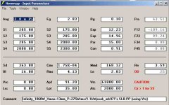
Hi,
Maybe look at the coupling duct the same as you would look at a vented enclosure (phase inverter/bass reflex: in phase at resonance, shuts off above)? Sine143 got ahead of me. Anyway, here is a Hornresp simulation for the SLBP-PP:
Regards,
Hi,
Maybe look at the coupling duct the same as you would look at a vented enclosure (phase inverter/bass reflex: in phase at resonance, shuts off above)? Sine143 got ahead of me
. Anyway, here is a Hornresp simulation for the SLBP-PP:Regards,
Attachments
Thanks for getting me back on track.this is the same issue all vented subs deal with.
at the port tuning (where there is actual output from the vent), the cone has very low displacement (thus there isnt very much output from the actual cone. as such it sums (with the added group delay of the vent output).
Ecxellent graph, thank youBrian,
If there is room for 6 inches of absorbent material, the plenum has been made too large
If the plenum is properly sized, the peaks will be around 180 Hz and above, almost an octave above a sub's usual pass band, and be of little concern with most crossovers, and easily equalized with DSP.
The frequency response chart below is from a 2x15" PPSL with a 7.5" x 15.25" x 15.25" plenum.
Art
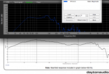
May I just check if that is un-EQ'd, close-mic measured output up to 1kHz?
If so, I presume the roll off above the peak is the LPF-effect of the slot/plenum?
I still haven't got my head round how a plenum acts as a LPF - in my head, bass frequency waves are 'bigger' so would be more constrained within a small slot, but it's the opposite?!
1) Speaker cabinet and mic were outdoors on the ground ("ground plane" measurement), mic is 2 meters from the cabinet front.1)May I just check if that is un-EQ'd, close-mic measured output up to 1kHz?
2)If so, I presume the roll off above the peak is the LPF-effect of the slot/plenum?
3)I still haven't got my head round how a plenum acts as a LPF - in my head, bass frequency waves are 'bigger' so would be more constrained within a small slot, but it's the opposite?!
2)Yes, the roll off above the peak is the LPF-effect of the slot/plenum, the factory response graph of the speaker is compared below to the PPSL.
More details are available in this thread about the cabinets:
http://www.diyaudio.com/forums/subw...using-dayton-pa385-8-drivers.html#post3898842
3) Low frequency waves are too long for the plenum to have any effect, it boosts the upper bass response of the speaker up to around 160 Hz, then band passes above. Even though Hornresp models circular enclosures, it still gives a fairly good prediction of the location of the peaks and dips which are specific to the plenum volume and depth which react like a stubby horn.
I had hoped to compare the contribution of the plenum's bandpass effect on distortion separate from the PP even order distortion reduction with the above mentioned build, but the cabinet was too small to fit the two 15" facing each other, so only measured PP.
Art
Attachments
Last edited:
Art,
Do you think the calculation for the vent/ plenum combo would be the same for vent separate from plenum? Combining them is an interesting idea.
It is not the same calculation at all. I have the simulation for this geometry in AkAbak - it is kind of like a tapped horn as the output radiation interacts with the front of the cones to produce a bandpass response. It is rather nice and flat.
Check out the sims here: http://www.diyaudio.com/forums/subwoofers/255959-sim-slbp_pp-maybe-more.html
Here is a sim with dual Eminence Sigma Pro 18's.
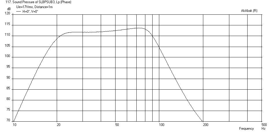
Sims are cute, check out the actual response of a cabinet similar to what you simulated, it won't be "nice and flat", but will be very usable in the real world of PA use, where one equalizes as needed.It is rather nice and flat.
Check out the sims
Build and measure, have fun
.Art
Attachments
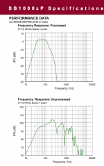
Thank you for the explanation, you are a gent, sir1) Speaker cabinet and mic were outdoors on the ground ("ground plane" measurement), mic is 2 meters from the cabinet front.
2)Yes, the roll off above the peak is the LPF-effect of the slot/plenum, the factory response graph of the speaker is compared below to the PPSL.
More details are available in this thread about the cabinets:
http://www.diyaudio.com/forums/subw...using-dayton-pa385-8-drivers.html#post3898842
3) Low frequency waves are too long for the plenum to have any effect, it boosts the upper bass response of the speaker up to around 160 Hz, then band passes above. Even though Hornresp models circular enclosures, it still gives a fairly good prediction of the location of the peaks and dips which are specific to the plenum volume and depth which react like a stubby horn.
I had hoped to compare the contribution of the plenum's bandpass effect on distortion separate from the PP even order distortion reduction with the above mentioned build, but the cabinet was too small to fit the two 15" facing each other, so only measured PP.
Art
The graph is very helpful - I have not seen it graphed before!I'm still not sure I understand the high/low frequency impacts of the slot - if it is acting as a horn then I need to get reading up on horn theory! I have not done so yet, which is probably why I'm not quite 'getting it' yet
so that is my fault IIRC one should model the horn 'length' as the measurement from the front baffle face to the centre-line of the drivers?
The increased high-bass output would be interesting to experiment with in a home cinema system - I have heard some systems crossed over at 400Hz and directionality wasn't an issue(!), and if I can take some stress off the speakers, it may help them play a little cleaner?
I am hoping I will be able to take some measurements of my build when it is complete, although I am unable to test GP, unfortunately, so will have to take measurements in-room and close-mic to try and remove the effects of the room from the recorded response...
In Hornresp, S1 is the area at the back of the "horn" (or plenum) S2 is the center of the drivers, S3 to S5 can be the baffle face. Using more than 3 points allow for experimenting with a flared exit.IIRC one should model the horn 'length' as the measurement from the front baffle face to the centre-line of the drivers?
The increased high-bass output would be interesting to experiment with in a home cinema system - I have heard some systems crossed over at 400Hz and directionality wasn't an issue(!), and if I can take some stress off the speakers, it may help them play a little cleaner?
Crossover points are always a compromise, if top speakers can't go below 400 Hz (well into the vocal range) without the level desired, I'd probably use front loaded rather than slot loaded woofers.
- Status
- This old topic is closed. If you want to reopen this topic, contact a moderator using the "Report Post" button.
- Home
- Loudspeakers
- Subwoofers
- A Thread for those interested in PPSL enclosures