From your question I can only deduce that you don't understand digital recordings. (A lot of people don't) The subject has been explained again and again in this thread. But I'm not embarrassed to repeat myself.
From your response I deduce that you miss my point entirely.
Let me restate: When you listen to your system at normal "high volume" that yields your 2.3v RMS, what it peak voltage?
I set up amplifier rated at 100watts rms into 8ohm load; That's a about 28.3 volts RMS. So I play 0dBFS sine signal with no digital attenuation and adjust preamp output until I see desired RMS voltage. Now to get 2.3v RMS I need only turn levels down about -21.8dB, or generate sine at -21.8dBFS.
Andrew
Easy - peak will be 2.3V x 1.414 = 3.25V.
But I can see that I made a mistake in post #694 by stating "RMS max voltage". 2.3V would be the peak output value at the setting where the reference tone measures 0.58V RMS. The phrase "RMS max voltage" does not belong in that poorly written sentence, or the value should be stated as 1.63V RMS. (0.58V RMS +9dB) Sorry about that.
What often leads to confusion (mine included) is that if a signal has an RMS value of -12dBFS, then it's 9dB below the loudest sine wave recordable. Because the loudest possible sine wave has an RMS value of -3dBFS. Its peaks will be at 0dB, full scale. Thus, if I measure the reference tone at 0.58V RMS, then the loudest, unclipped sine wave output will be 1.63V RMS (9dB higher than the tone measurement), with peaks at 2.3V (12dB higher than the tone measurement). The reference tone does not have to be set at -12dBFS, it was just a convenient value.
As to the second part with the 100 watt amp, yes, that makes sense. From 28.3 volts to 2.3 volts is about 22dB attenuation. But I am missing the point. How does that relate to the reference tone? Can you explain further?
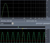
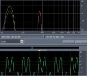
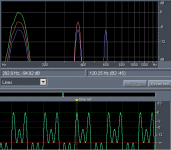
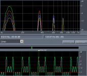
Let's take a closer look at how 0dBFS mixes of multiple equal levels sines behave.
Single sine 0dBFS reference:
Two tones:
Three tones:
Four tones:
Five tones:
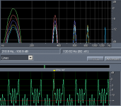
As signal complexity grows, each component shares bandwidth.
Here is 120Hz sine with broadband transient:
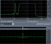
and zoom of above view showing 120Hz sine has signal peak of -52dB relative to full scale:
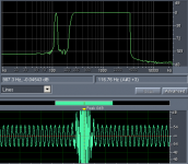
Applying this to your peak of 3.25 volts means using a single amplifier would require it to produce peak voltage of about 1294 volts to get unclipped output.
I've include an mp3 of 120Hz sine with 10 bursts as above, with extension changed to zip. Just change back to mp3 to explore it.
Regards,
Andrew
Single sine 0dBFS reference:

Two tones:

Three tones:

Four tones:

Five tones:

As signal complexity grows, each component shares bandwidth.
Here is 120Hz sine with broadband transient:

and zoom of above view showing 120Hz sine has signal peak of -52dB relative to full scale:

Applying this to your peak of 3.25 volts means using a single amplifier would require it to produce peak voltage of about 1294 volts to get unclipped output.
I've include an mp3 of 120Hz sine with 10 bursts as above, with extension changed to zip. Just change back to mp3 to explore it.
Regards,
Andrew
Attachments
Let's take a closer look at how 0dBFS mixes of multiple equal levels sines behave.
...
Applying this to your peak of 3.25 volts means using a single amplifier would require it to produce peak voltage of about 1294 volts to get unclipped output.
I am lost, I cannot follow the argument. Can you say more about what "this" is that you are applying?
Yeah, I'm lost too.
Thanks for the work on the additive tones, tho. From those we see that peak level never goes above 0dB - as one would expect. As things get louder and louder the RMS value of the signal will go up, but the peaks will never be above 0dB. They can't be, nothing above 0dB exists.
That's the main point of this test and survey. If you measure the voltage of a digital tone with a known value, then all other values will be known to you. Maximum possible voltage will be easy to determine.
Just as a sanity check I did this test again tonight with a level that is not super loud, but as loud as I normally listen. (plenty loud) Got 0.58V on the 120Hz signal.
That puts me at 2.3 volts RMS max voltage I need at that volume setting. Obviously, I have efficient speakers. I need current gain more than voltage, really. That would change fast with less efficient speakers and/or a larger space.
Hey same as me, very close to my 3.5 volts ...
Yeah, I'm lost too.
Thanks for the work on the additive tones, tho. From those we see that peak level never goes above 0dB - as one would expect. As things get louder and louder the RMS value of the signal will go up, but the peaks will never be above 0dB. They can't be, nothing above 0dB exists.
That's the main point of this test and survey. If you measure the voltage of a digital tone with a known value, then all other values will be known to you. Maximum possible voltage will be easy to determine.
I'm not sure why you are lost, when it is easy to determine; with my example test signal you can loop a segment between bursts, and now you are playing a 120Hz sine wave. If volume is turned up until 120Hz sine is 3.25 volts peak, the corresponding peak of burst at 0dBFS is 52dB higher. Doing the math, 52dB works out to about 398x, and thus multiplying out with 3.25 peak volts yields peak voltage of 1294v for peak signal in track.
So reality with broadband test signals is you can do high power testing of amplifiers and drivers in large signal domain without excessive heat build up.
Regards,
Andrew
Wow Andrew, you really don't understand the test. You are looking at it from completely the wrong angle. You're looking bottom up, instead of top down. Once you see your error, you'll slap yourself on the forward and say "Doh!" 
I have explained it over and over again throughout the thread. Perhaps you can read back a bit, or take it from the top. I'll try to find the relevant posts for you and point to them.
I have explained it over and over again throughout the thread. Perhaps you can read back a bit, or take it from the top. I'll try to find the relevant posts for you and point to them.
Pano has been very patient in explaining this over and over again. Please do him the courtesy of reading the previous posts so you can understand what is being said.Yes, your test demonstrates what voltage it takes to play a single frequency as loud as it occurs in program material, it tells nothing about power to play broadband signal. Slap yourself on your head and say "Doh!" for me.
Thanks,
Andrew
Yeah, but you use way more current than I do, right?
Well a true current speaker ..... Right !!!
Andrew, have you actually read the first few posts? I suggest that you do. You are still thinking bottom up, not top down. Therein lies your misunderstanding of the method.
Going back to your post about the 100W/8 ohm amp that can supply 28.3 volts RMS. How did it get rated at 100W? The amp will be tested on a sine wave. It has to be able to supply 28.3 volts RMS into 8 ohms (40V peak). A sine wave is a very hot signal. Even the loudest, most compressed musical passages are rarely hotter than -8dB RMS. About 1/3 the RMS power of a simple sine wave.
The point of the test is clipping. Simply that, no more. Digital signals NEVER exceed 0dB. Single tone, multi-tone, noise, music, speech, broadband, narrow band, whatever. The peak will never be above 0dB. Once you measure and know what the output voltage of 0dB is, you know that all other voltages must be below that. The highest the power you could ever get would be that voltage squared, divided by R. W=V2/R. That's peak power. All other power will be below that. A sine wave exactly 3dB below peak. Other signals will be different, but generally lower, not that it really matters here.
E.G. If you set your loudest level with a dynamic music track, then measure the amplifier output voltage of my reference tone at 10 volts RMS, you'll know that 0dBFS will correspond to 40V, peak. +12dB .... Or 28.3V RMS on a sine wave. Voila, you are just hitting the max voltage and RMS power of your 100W amp. You may want to get a bigger amp. Even adding 100s of single tones together, the output would never go above 40V peak. The RMS value would depend on the composite waveform of all those tones, but it's unlikely to be higher than -3dB peak, or 100 watts into 8 ohms.
Does that answer your concerns about the power needed for complex program material? Once you know its absolute peak value, you know the maximum power from Ohm's law. All other power must be below that, no matter what the waveform.
Correct! But not the point. Because it does not matter. Once you know what the peak voltage will be, then ALL other voltages must be lower. It's that simple. Yes, as I have recently noted, the RMS value of a signal can change based on its waveform, but it will always be lower than peak. Peak is the highest it can go. It's called 0dBFS in the digital realm....it tells nothing about power to play broadband signal
Going back to your post about the 100W/8 ohm amp that can supply 28.3 volts RMS. How did it get rated at 100W? The amp will be tested on a sine wave. It has to be able to supply 28.3 volts RMS into 8 ohms (40V peak). A sine wave is a very hot signal. Even the loudest, most compressed musical passages are rarely hotter than -8dB RMS. About 1/3 the RMS power of a simple sine wave.
The point of the test is clipping. Simply that, no more. Digital signals NEVER exceed 0dB. Single tone, multi-tone, noise, music, speech, broadband, narrow band, whatever. The peak will never be above 0dB. Once you measure and know what the output voltage of 0dB is, you know that all other voltages must be below that. The highest the power you could ever get would be that voltage squared, divided by R. W=V2/R. That's peak power. All other power will be below that. A sine wave exactly 3dB below peak. Other signals will be different, but generally lower, not that it really matters here.
E.G. If you set your loudest level with a dynamic music track, then measure the amplifier output voltage of my reference tone at 10 volts RMS, you'll know that 0dBFS will correspond to 40V, peak. +12dB .... Or 28.3V RMS on a sine wave. Voila, you are just hitting the max voltage and RMS power of your 100W amp. You may want to get a bigger amp.
Does that answer your concerns about the power needed for complex program material? Once you know its absolute peak value, you know the maximum power from Ohm's law. All other power must be below that, no matter what the waveform.
another ill-formed Member !..................Applying this to your peak of 3.25 volts means using a single amplifier would require it to produce peak voltage of about 1294 volts to get unclipped output.
more of the same !now you are playing a 120Hz sine wave. If volume is turned up until 120Hz sine is 3.25 volts peak, the corresponding peak of burst at 0dBFS is 52dB higher. Doing the math, 52dB works out to about 398x, and thus multiplying out with 3.25 peak volts yields peak voltage of 1294v for peak signal in track.
Let's look at analogue. Forget digital for the moment.
Take a 1Vac sinewave @ 120Hz.
Add a 1Vac sinewave at 2000Hz.
The combined dual frequency signal has a peak voltage of 2.83Vpk when the crests of both sinewaves exactly coincide. That could be @ -2.83Vpk or at +2.83Vpk.
Now let's add another sinewave again 1Vac but at 5kHz.
The worst case peak voltage in the signal of the three sinewaves is 4.24Vpk.
Now we move to digital recording.
The digitiser samples the signal and there will be a coding for the 4.24Vpk that exactly equals the 0dBfs.
When the digitised signal is unscrambled back to analogue the three sinewaves will be there (provided the "system" has not added noise nor distortion) and each will be of equal level.
All three sinewave peaks will "add" up to that analogue output level that is exactly equal to the 0dBfs in the digital doamin.
If the player has a maximum analogue output of 3Vpk, then the three sinewaves will each be at a level of 1Vpk. i.e. each will be at a level of 707.1mVac.
No matter how few, or how many sinewaves are in the music/audio signal, the maximum output from the digital recorder can never be above the analogue equivalent of that 0dBfs, never ever!
All the signals summed must not exceed that level or they will be clipped in the digital recorder. That clipped or unclipped maximum output can never exceed the analogue equivalent of that 0dBfs value.
Last edited:
I generally read OP before posting to a thread, and that is the case here. There is no misunderstanding of the presented test and intent of thread. Mostly having fun.
This is true for a simple sine, but Gibbs effect comes into play, and level between two sample may, and often will be higher or lower than either sample.
Here is simple case: With sample rate 48kHz, a 0dBFS 12kHz sine wave may be represented with as repeating sequence of four samples valued at -0dB,-0dB,0dB,0dB.
A connect the dot approach leads to conclusion that a square wave has been specified, and is incorrect.
A perfect sine wave passes through sequence of points and crests 3dB higher.
MLS sequences are constructed with only two sample values too, and reconstructed output has peaks 6dB greater.
Regards,
Andrew
All the signals summed must not exceed that level or they will be clipped in the digital recorder. That clipped or unclipped maximum output can never exceed the analogue equivalent of that 0dBfs value.
This is true for a simple sine, but Gibbs effect comes into play, and level between two sample may, and often will be higher or lower than either sample.
Here is simple case: With sample rate 48kHz, a 0dBFS 12kHz sine wave may be represented with as repeating sequence of four samples valued at -0dB,-0dB,0dB,0dB.
A connect the dot approach leads to conclusion that a square wave has been specified, and is incorrect.
A perfect sine wave passes through sequence of points and crests 3dB higher.
MLS sequences are constructed with only two sample values too, and reconstructed output has peaks 6dB greater.
Regards,
Andrew
Have you read my post?.....................
This is true for a simple sine, but Gibbs effect comes into play, and level between two sample may, and often will be higher or lower than either sample.
Here is simple case: With sample rate 48kHz, a 0dBFS 12kHz sine wave may be represented with as repeating sequence of four samples valued at -0dB,-0dB,0dB,0dB.
A connect the dot approach leads to conclusion that a square wave has been specified, and is incorrect.
A perfect sine wave passes through sequence of points and crests 3dB higher.
MLS sequences are constructed with only two sample values too, and reconstructed output has peaks 6dB greater.
I put it there for you.
So you are saying that a DAC can output a voltage 6dB higher than its 0dB peak? There was discussion of this earlier in the thread, but it didn't go very far. I have yet to see it, but could certainly look for it on the o'scope with MLS signals. To date, I don't remember anyone actually showing that happening on music, but I'd have to dig back thru the thread.MLS sequences are constructed with only two sample values too, and reconstructed output has peaks 6dB greater.
The point of this test is to determine what voltages your amplifier outputs on the very loudest passages you listen to. It does that just fine. So far there have been few (maybe 2) who have measured and found that they lacked headroom at the loudest volumes. And that's the main idea of the test, how much headroom do you have, or not have. There is also a survey (poll) to get an idea of the range of voltages normally encountered on systems owned by diyAudio members.
There is a line between "having fun" and trolling or wasting people's time. Please don't cross it.
Yes, Pano
Thank you for this thread;please forgive my diversions.
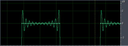
I've done plenty with o'scope, and behavior of MLS is true. It is very harsh signal, often demanding maximal slewing. 0dBFS square wave is also harsh, and is classical demonstration of Gibbs effect. One of Cool Edit software features is waveform display shows very good virtual behavior in similarity to real deal on o'scope; 1kHz square wave, 0dBFS sample rate 48kHz:
Regards,
Andrew
Thank you for this thread;please forgive my diversions.
I've done plenty with o'scope, and behavior of MLS is true. It is very harsh signal, often demanding maximal slewing. 0dBFS square wave is also harsh, and is classical demonstration of Gibbs effect. One of Cool Edit software features is waveform display shows very good virtual behavior in similarity to real deal on o'scope; 1kHz square wave, 0dBFS sample rate 48kHz:

Regards,
Andrew
- Home
- Loudspeakers
- Multi-Way
- A Test. How much Voltage (power) do your speakers need?