Your Prototyping setup
Hello Glenn
What setup do you use to etch PCBs do you use a special heated tank , is it positive or negative process , how do you generate your films and where do you get your supplies from.
I use to etch my own boards but found that my etching was not consistent across the board with the process I used.
By the way what to you use as a speaker protection relay.
Regards
Arthur
Wow! and thank you. This amp is both inspireing and humbling ( great to know what kind of leading edge performance is possible, even if getting there might not be (for me).
Hate to ask of things from such a busy guy but: I have been playing with two pole compensation and would love to see the loopgain plot of this amp, is it flat out to 20 k, is there a peak before it starts to drop?
Hate to ask of things from such a busy guy but: I have been playing with two pole compensation and would love to see the loopgain plot of this amp, is it flat out to 20 k, is there a peak before it starts to drop?
Re: Your Prototyping setup
Hi Arthur
All the stuff I use is avaliable from here:
http://www.computronics.com.au/kinsten/
I print my transparancies on a Epson "Stylus Colour 3000" bubble jet. That gives a nice, solid black print.
Cheers,
Glen
PHEONIX said:Hello Glenn
What setup do you use to etch PCBs do you use a special heated tank , is it positive or negative process , how do you generate your films and where do you get your supplies from.
I use to etch my own boards but found that my etching was not consistent across the board with the process I used.
By the way what to you use as a speaker protection relay.
Regards
Arthur
Hi Arthur
All the stuff I use is avaliable from here:
http://www.computronics.com.au/kinsten/
I print my transparancies on a Epson "Stylus Colour 3000" bubble jet. That gives a nice, solid black print.
Cheers,
Glen
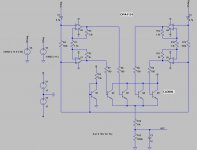
G.Kleinschmidt said:Anyone out there who has tried out the Blameless with two-pole compensation may have noticed that the amplifier then develops horrible, asymmetric squarewave, clipping and clipping recovery performance.
This is due to a number of issues - here the mods and additions I have made to address all of them.
Firstly, a voltage clamp consisting of D3-D6 and transistors Q10 and Q11 is added which prevent saturation of the VAS transistor Q7 and its current source Q9. This comes at only a small cost to the output voltage swing.
Secondly, the LTP is provided with a 3-transistor current source and the VAS has an emitter degeneration resistance of 24 ohms. In this case the VAS standing current is 9mA and the LTP tail current is 5mA.
The result of this is that the quiescent, or DC voltage at the collector of each long tail pair transistor is equal.
This allows two back-to-back limiting diodes, D1 and D2, to clamp the maximum AC drive voltage to the VAS emitter follower symmetrically at +/-700mV.
This has two very important benefits. Firstly, it makes it impossible for the current mirror transistors to saturate. Secondly, the +/-700mV limited output swing automatically provides a current limit for the VAS, being equal to 700mV/24 ohms (R17), or ~30mA.
Hi Glenn,
Great minds think alike. This is indeed a good circuit.
Take a look at D5 & 6, Q18 & 19 in my MOSFET EC amplifier paper. Your Baker clamp is essentially the same thing.
Your pair of diodes clamping the output of the LTP can also be seen in that design.
The collector currents in Q18 & 19 can also be used to do interesting things, such as a clipping indication and also closed-loop clamping; I actually used the latter approach to get rid of the slight amount of sticking in my circuit (due to the R-C in the collectors of my LTP for Miller loop compensation) that you had expressed concern about awhile back. A portion of the joined collector signal is fed back to the LTP feedback node.
Cheers,
Bob
Hi Bob.
I have a question on an entirely different topic. Which came first, the Cordell THD analyser or the AP system 1 (full service manual downloadable here: http://ap.com/download/discontinued) ?
Despite the fact that jfets are used to switch in the timing capacitors and proprietary low distortion multiplying DAC’s (I suspect similar to the AD7110) are used to set the frequency / trim loop gain, the generator (oscillator) section is pretty much identical to yours.
The state variable filters loop gain is set a little higher than unity and an opamp based multiplier (with jfet control) is used for amplitude control.
I’m currently building my own version of the (PC controlled) AP1. However to keep the generators THD as low as possible I’m going to use relays to switch the timing capacitors. For the timing resistances (of the integrators) I’m going to use a dual gang potentiometer. Its shaft will be coupled to a small DC motor via a reduction gearbox.
A uC based frequency meter and servo controller will control all of this, auto tuning the frequency to the desired value.
A Vishay VCR2N "variable resistor” (very linear) will be used in the multiplier for the amplitude control, and modern opamps throughout.
I figured that I can used the quadrature outputs from the intergrators to make a 4-phase rectifier (based on a pair of unity gain inverters and an LM3086 five NPN transistor array – the fifth, substrate connected transistor used for biasing) to keep the AGC loop ripple really low.
Cheers,
Glen
cbdb said:Wow! and thank you. This amp is both inspireing and humbling ( great to know what kind of leading edge performance is possible, even if getting there might not be (for me).
Hate to ask of things from such a busy guy but: I have been playing with two pole compensation and would love to see the loopgain plot of this amp, is it flat out to 20 k, is there a peak before it starts to drop?
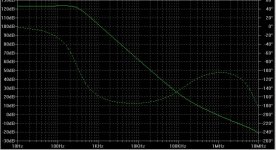
Hi, here is the loop gain plot. There is a small peaking but it starts rolling off a lot earlier than 20kHz!.
The roll-off starts at -12dB/octave (2-pole), accumulating approximately 180 degrees of phase shift, reverting back to a single pole response (-6db/octave, ~90 degrees) at approximately 1/5th the unity loop gain frequency.
Cheers,
Glen
Attachments
G.Kleinschmidt said:Yes, I'm using separate rails for the CFB OPS and the input stage/VAS, which means that the VAS clamping arrangement is a little different.
The problem with the nfb clamp and the unipolar VAS is that while the VAS transistor can supply all the current the feedback network requires on positive clipping, the current on negative clipping is limited to the VAS CCS current.
I was worried about the VAS voltage clamp referenced to the power output stage rails feeding high frequency switching spikes via the diode junction capacitances into the VAS output, but the issue is rather small and can be, for all practical purposes, completely eliminated with just some light RC filtering between the OPS supply rails and the VAS voltage clamp.
A LF pole of one hundred Hz or so is ample and the clamp will track any supply rail droop occuring with any bass transient.
Cheers,
Glen
Hi Glen,
Agreed. BTW, in the past, you were a fan of a complementary VAS and TMC. Why this switch? just because you want to explore all possible configurations?
Cheers,
Edmond.
Edmond Stuart said:
just because you want to explore all possible configurations?
Yup.
On an entirely different note, here is my 4-phase rectifier for the AGC loop of the State Variable oscillator. Uses one OPA4134 quad jfet input opamp and one CA/LM 3086 five NPN trannie array.
For the 4 opamps that make up the state variable oscillator, I'll use a pair of LM4562 duals.
Cheers,
Glen
Attachments
G.Kleinschmidt said:
For the 4 opamps that make up the state variable oscillator, I'll use a pair of LM4562 duals.
Why not using this: http://focus.ti.com/lit/ds/symlink/mpy634.pdf It's excellent up to 500-600KHz.
Save some effort to find high precision components (in particular caps) and use this:
http://focus.ti.com/lit/ds/symlink/uaf42.pdf
Free samples available from TI. I used both to build a SVO three years ago, and got excellent results up to 500KHz.
G.Kleinschmidt said:Hi Bob.
I have a question on an entirely different topic. Which came first, the Cordell THD analyser or the AP system 1 (full service manual downloadable here: http://ap.com/download/discontinued) ?
Despite the fact that jfets are used to switch in the timing capacitors and proprietary low distortion multiplying DAC’s (I suspect similar to the AD7110) are used to set the frequency / trim loop gain, the generator (oscillator) section is pretty much identical to yours.
The state variable filters loop gain is set a little higher than unity and an opamp based multiplier (with jfet control) is used for amplitude control.
I’m currently building my own version of the (PC controlled) AP1. However to keep the generators THD as low as possible I’m going to use relays to switch the timing capacitors. For the timing resistances (of the integrators) I’m going to use a dual gang potentiometer. Its shaft will be coupled to a small DC motor via a reduction gearbox.
A uC based frequency meter and servo controller will control all of this, auto tuning the frequency to the desired value.
A Vishay VCR2N "variable resistor” (very linear) will be used in the multiplier for the amplitude control, and modern opamps throughout.
I figured that I can used the quadrature outputs from the intergrators to make a 4-phase rectifier (based on a pair of unity gain inverters and an LM3086 five NPN transistor array – the fifth, substrate connected transistor used for biasing) to keep the AGC loop ripple really low.
Cheers,
Glen
Hi Glenn,
The Cordell Distortion Analyzer came before the AP System 1. I published my analyzer in Audio in July 1981. I had completed the unit about a year earlier. Audio Precision wasn't founded until 1984.
Cheers,
Bob
Bob Cordell said:
Hi Glenn,
The Cordell Distortion Analyzer came before the AP System 1. I published my analyzer in Audio in July 1981. I had completed the unit about a year earlier. Audio Precision wasn't founded until 1984.
Cheers,
Bob
I think Bruce worked for Tek on their similar products, I have no idea how much of a departure the AP1 was.
scott wurcer said:
I think Bruce worked for Tek on their similar products, I have no idea how much of a departure the AP1 was.
Hi Scott,
Yes. AP founders Bruce Hofer and Rich Cabot are old friends of mine from their days at Tek Bruce was in charge of the SG505 and AA501 oscillator and analyzer TM500 plug-ins.
Cheers,
Bob
Hi, here is the loop gain plot. There is a small peaking but it starts rolling off a lot earlier than 20kHz!.
Thanks for the reply. Wow thats a lot of open loop gain! Looks similar to my 2 pole plots. One more question: Dont you measure the phase margin as the minimum margin before the 0db crossing, ie. about 10 degrees? Do lower freq square waves ring? or does the large amount of feedback take care of these prolems? Sorry for all the questions but I have been trying to figure out a way to get rid of this first phase dip; am I wasting my time?
phase dip
Most likely only overshoot, so no ringing
No.
Use TMC instead of TPC.
It depends on your goal. TPC lowers the distortion from the VAS and the OPS, while TMC only reduces the distortion from the OPS.
Cheers,
Edmond.
cbdb said:Thanks for the reply. Wow thats a lot of open loop gain! Looks similar to my 2 pole plots. One more question: Dont you measure the phase margin as the minimum margin before the 0db crossing, ie. about 10 degrees? Do lower freq square waves ring?
Most likely only overshoot, so no ringing
or does the large amount of feedback take care of these prolems?
No.
Sorry for all the questions but I have been trying to figure out a way to get rid of this first phase dip;
Use TMC instead of TPC.
am I wasting my time?
It depends on your goal. TPC lowers the distortion from the VAS and the OPS, while TMC only reduces the distortion from the OPS.
Cheers,
Edmond.
G.Kleinschmidt said:I was worried about the VAS voltage clamp referenced to the power output stage rails feeding high frequency switching spikes via the diode junction capacitances into the VAS output, but the issue is rather small and can be, for all practical purposes, completely eliminated with just some light RC filtering between the OPS supply rails and the VAS voltage clamp.
A LF pole of one hundred Hz or so is ample and the clamp will track any supply rail droop occuring with any bass transient.
One thing I was looking at was putting a diode in parallel with the resistor of this LPF, giving a "min hold" function. The time constant of the filter can be made quite long while still allowing it to track sudden drops in the output stage supply.
- Status
- This old topic is closed. If you want to reopen this topic, contact a moderator using the "Report Post" button.
- Home
- Amplifiers
- Solid State
- A superior VAS clamp and VAS current limit for the Blameless.