Conclusion continued...
This picture it is the specifications given by Motorola for this 200W amplifier. The voltage slew rate it is given as 125V/ìsec.
Try a calculation and you can find that the slew rate indicated in Motorola curve it is 60V/ìsec as much. Is this method of calculation propper? Or the slew rate given in this table it is fake?
Attachments
The answeer...
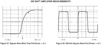
Probably, the method that used for the measurement of slew rate of 125V/ìsec it is seperate from the measurement presented in curves showing the output rise time (under real conditions because you can't measure a full output square under an 8Ù load with the feedback loops open).
Dirty Harry has a bandwidth limitted at 170KHz. This is given by the equation: BW = 0,34 / rise time = (0,34 / 2ìsec) X 10^6.
It is more than enough for its work.
I don't know how much is its real slew rate.
From curiosity, i followed some propositions of Glen Kleinschmidt to increase the degeneration resistors and to reduce the Cdom, but nothing changed. Glen, did his right calculations of course but there is also another one obstacle in improvement of S.R., the beast MJE15032 in the VGS (as notted very rightly by ostripper).
Anyway, if you want a very big slew rate, you can modify the input with double LTPs, you can change the VGS transistors with Toshiba, or you can implement one Giovanni Stochino or a Randy Slone amplifier (are almost same between them) but - i think - with lower supply level from dirty harry to don't replace every day burned output transistors or VAS transistors.
Dirty Harry circuitry and construction is based on commercial PA amplifiers from which i have an expertise of service about 25 years.
Finally, i get back anything i told in Glen and i wish to be friend with him. I am sorry, because from my mulishness it is under moderation (like me also) this moment.
Glen, i hope you will accept the friendship hand that i offer to you.
Fotios
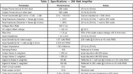
lineup said:Can it be that one value is for full voltage output
and one is for 50% of full voltage?
Hi Lineup
I don't think so, but i am not sure for this. Because in both graphs, i think the vertical scale it is the same, 20V/div.
Fotios
Did you see that Nico Ras amplifier .. where he told 580V/uS.
But this is very difficult to believe.
Even 58V/uS would be a very fast power amplifier.
Fast Class A Amp
http://www.diyaudio.com/forums/showthread.php?s=&threadid=132790
There are several very good audio OpAmps chips having like 10-25 V/uS.
And this is at much, much lower currents.
But this is very difficult to believe.
Even 58V/uS would be a very fast power amplifier.
Fast Class A Amp
http://www.diyaudio.com/forums/showthread.php?s=&threadid=132790
There are several very good audio OpAmps chips having like 10-25 V/uS.
And this is at much, much lower currents.
lineup said:Did you see that Nico Ras amplifier .. where he told 580V/uS.Fast Class A Amp
http://www.diyaudio.com/forums/showthread.php?s=&threadid=132790
Very amusing thread.
But i am in a bad mood these days. Have you looked in your forum?
Fotios
Lineup, such slewrates are possible with output stages with gain, mikeks some years back liked this kind of scheme for improving slewrate. What I cannot understand from Nico s design is that he says its single ended, how to get gain from that. A thought just came up as he uses mosfets so probably a cfp of a bjt and mos with gain.
Fotios this is a nice design, bearing in mind its for PA use I would say its build like a truck, to last. For home use one could always refine some components to get max sound quality performance but for for PA its very good indeed. If one uses most of these diy amps here for PA use especially in clubs youd see plenty of smoke. In my youth I worked as a Pro DJ in a large club for 8 years and blew maybe close to 200 amps. We were using 10 400 watters to blast house music through the ears of frenzied teenagers. The ones blowing were most often the fancy designs but better sounding ones, while the more rugged ones with over the board driver and output components never gave up the bliss.
Fotios this is a nice design, bearing in mind its for PA use I would say its build like a truck, to last. For home use one could always refine some components to get max sound quality performance but for for PA its very good indeed. If one uses most of these diy amps here for PA use especially in clubs youd see plenty of smoke.
In my youth I worked as a Pro DJ in a large club for 8 years and blew maybe close to 200 amps. We were using 10 400 watters to blast house music through the ears of frenzied teenagers. The ones blowing were most often the fancy designs but better sounding ones, while the more rugged ones with over the board driver and output components never gave up the bliss.dirty harry
hi fotios
greetings i want to make dirty harry for subwoofers can you
tell me a few thing so i can make it sucessfully
1 driver transistors not available can i use mj150022 mj150023
2 heatsink fischer model not available so your pcb cannot be used
spent whole day to etch it then put only to find heat sink not available
can i draw smaller pcb to test it only small wires to output tran will
sound degrade or any problems will be caused like ossicilation
3 value of bias preset 500 ohms or 5k like zak
4 are base stopper resistance 10 ohms necessary
5 your method of biasing it and any special construction hints
6 one part 12 ohms 5 watt not available only 3 watts available
or 15 ohms 5 watt available what to use
hoping you can help will show pics of progress and of what i mean i had written to you before you had put pcb design on diy
ready to make dirty harry hoping you will oblige
thanking you
andrew lebon
Hi andrewledon
I promise to reply in detail, but first i must do a relativelly long research and some drawings to show you some things like a different arrangement of different heatsinks for forced air cooling. Also i must check again the values of parts in my prototype as well the propper voltage values in some points to post so you can have a refference.
You must try to build compact pcbs, no wires instead tracks. It is mandatory this because the danger of thermal runaway. In this maner, forget base stoppers etc. These are necessary for other type outputs and arrangements. Here, not.
Be patient please for 1 to 2 days to get my reply.
By the chance given, what type of heatsinks are offered in your place? Inform me please to think a different shape of the air tunel.
Regs
Fotios
as about specs and spec freaks
it is been clearly stated many times before and i will do it one more time ...... will also chalenge anyone to state otherwise ....
of course the basic diference between a forum amp ( almost any forum amp ) and DIRTY HARRY is the abuse word
i bet you that you might have many amps that sound better than DIRTY HARRY but how much abuse can they stand ?????
check quasi's amps for example a very simple approach producing a lot of power versions up to 200W but then will they stand any abuse ???? i think not
check rods P101 also powerfull thingy to you think that is made for heavy PA use ???? i think not
what i am trying to say is that if you design any amp and then you need a lot of power but also stability and reliability against any possible abuse like use with low loads or and hard PA application then ofcourse you will loose some quality to gain safety ...... so trying to compair DIRTY HARRY with pass designs is a joke !!!! it will never happen ...... also trying to simulate will also bring insecure results ...... fotios said it very correct ..... to manufacture an amp like that require various skills and also producing a lot of power with a safety aspect is not an easy thing
also i think that my friend fotios and my friend glen have some issue ..... but i also think that it will be very funny to watch this batle going on since i beleive that these two people will never find a common ground because both of them are very good designers but design diferent things ......
andrewlebon said:please see the pictures
Hi Andrew
The correct schematic it is that presented in post "39". I have checked the values of parts used in the prototype board, and i can confirm you for this. The trimmer it is 500R multiturn, and the Vbe multiplier it is MJE340. Of course there is the option of use the more sensitive in temp variation BD137... it is your choice. The predicted Iq per output transistor, it is 25mA. You can measure it with a DC voltmeter accross one emitter resistor (the big 0,33R/10W): V = Iq X R=25mA X 0,33Ù = 8,25mV. Or you can place the DC voltmeter accross the C-E junctions of Vbe multiplier and turn the trim-pot to obtain 3,5V.
But this is not a simple proccess as i described... you must wait for 3/4 of an hour - at least - after the first callibration, because the Iq will be increased untill the heatsink will get a temp of 40C approx. Then you must readjust the trimpot so as the Iq restored at 25mA.
Please... don't make hasty actions, these projects demands big patience and attention... unless your amp will end up with burned resistors, shorted transistors etc. and it is a crime to spend money for new devices and time for repairs. I am here to offer my help.
As i said, it is wrong the mounting of output transistor rows - included drivers and predrivers and Vbe multiplier - in seperate heatsinks, according to the present circuit drawing.
Fotios
Re: very nice of you
Ah Saki... i know what you mean. In sequence --> --> --> -->
  -->
--> 
Thanks friend
Fotis
sakis said:fotios ....detailed presentation......
often designers throw a schematic and rest of these details is for the constructor to find out
regards sakis
Ah Saki... i know what you mean. In sequence -->
--> --> --> --> Thanks friend
Fotis
dirty harry
hi fotios
greetings have powered up the amplifier using 50 0 50 volts
ac secondary with 100 watt series bulb
1 with 500 ohms preset fully tuned clockwise bulb did not go off still
in series with input music sound was very very clear highs and lows
2 input transistors are heating up cannot touch with fingers and 1 kiloohm resistance gets charred q3 2n5401 connected to 220 seems
to get much to hot wonder what could be wrong is it because i connected 47 kilo ohm resistor from ground to input of 22 uf input
condenser non polar
3 both heat sinks are connected together by 5mm aluminum sheet
aluminium welded for heat transfer so this should not be the prob
4 speaker load impedance is 4 ohms
5 how do you match your transistors output as well as drivers
hoping you can tellme where i have gone wrong
bye
thanking you
andrew lebon
The LTP current source is delivering too much. Quickly try "replacing" it with a 47-68k resistor (high rail to LTP emitters). That will put it at about the right current w/no active device. If that fixes the input stage heating (and overcurrent in the amp) then the current source is the source of the trouble. The current source transistor may be bad, hooked up backwards, or even... fake.
Re: dirty harry
Hi Andrew
With 2 X 50VAC secodary you must have about +/-68VDC supply rails, and it's OK.
1. Please don't adjust the 500R preset without observing with a DMM the voltage drop accross an emmiter resistor to obtain a 25mA iddle current per output transistor. I described in previous post the procedure.
2. Have you measured the current flow thru R3? Place a DMM accross R3 and multiply the incicated voltage level with 220 to get the value of current of CCS. Do the same in R5, the current must be of the same value. The CCS feeds the LTP with a tail current of: I=0,65/220=2,95mA... the voltage drop accross R5 is: V=1K X 2,95mA = 2,95V thus the power dissipation in R5 is: P=2,95V X 2,95mA=8,7mW and it is very small to burn out R5. Also 2N5401 have an Ic=500mA, thus they have not problem with 2,95mA/2=1,5mA per device. Check for any error in parts place and in pcb tracks please.
3. It is OK if the heatsinks are WELDED between them, but the Vbe multiplier Q10 must be placed on the 5mm alu sheet to track the junction temperature of output transistors.
4. No problem with 4 ohm load.
5. It is good thing the matching of output transistors, i made allways this. There is somewhere a thread where you can find practical methods to do this. Please search my posts to find it. For the LTP transistors, if you don't match them, then you will have a DC offset as much 10mV in output due to the help of current mirror Q5-Q6... 10mV is an acceptable DC offset. It is your choice to match Q1-Q2 if you want a zero DC offset in output.
Regs
Fotios
andrewlebon said:hi fotios
greetings have powered up the amplifier using 50 0 50 volts
ac secondary with 100 watt series bulb
1 with 500 ohms preset fully tuned clockwise bulb did not go off still
in series with input music sound was very very clear highs and lows
2 input transistors are heating up cannot touch with fingers and 1 kiloohm resistance gets charred q3 2n5401 connected to 220 seems
to get much to hot wonder what could be wrong is it because i connected 47 kilo ohm resistor from ground to input of 22 uf input
condenser non polar
3 both heat sinks are connected together by 5mm aluminum sheet
aluminium welded for heat transfer so this should not be the prob
4 speaker load impedance is 4 ohms
5 how do you match your transistors output as well as drivers
hoping you can tellme where i have gone wrong
bye
thanking you
andrew lebon
Hi Andrew
With 2 X 50VAC secodary you must have about +/-68VDC supply rails, and it's OK.
1. Please don't adjust the 500R preset without observing with a DMM the voltage drop accross an emmiter resistor to obtain a 25mA iddle current per output transistor. I described in previous post the procedure.
2. Have you measured the current flow thru R3? Place a DMM accross R3 and multiply the incicated voltage level with 220 to get the value of current of CCS. Do the same in R5, the current must be of the same value. The CCS feeds the LTP with a tail current of: I=0,65/220=2,95mA... the voltage drop accross R5 is: V=1K X 2,95mA = 2,95V thus the power dissipation in R5 is: P=2,95V X 2,95mA=8,7mW and it is very small to burn out R5. Also 2N5401 have an Ic=500mA, thus they have not problem with 2,95mA/2=1,5mA per device. Check for any error in parts place and in pcb tracks please.
3. It is OK if the heatsinks are WELDED between them, but the Vbe multiplier Q10 must be placed on the 5mm alu sheet to track the junction temperature of output transistors.
4. No problem with 4 ohm load.
5. It is good thing the matching of output transistors, i made allways this. There is somewhere a thread where you can find practical methods to do this. Please search my posts to find it. For the LTP transistors, if you don't match them, then you will have a DC offset as much 10mV in output due to the help of current mirror Q5-Q6... 10mV is an acceptable DC offset. It is your choice to match Q1-Q2 if you want a zero DC offset in output.
Regs
Fotios
- Status
- This old topic is closed. If you want to reopen this topic, contact a moderator using the "Report Post" button.
- Home
- Amplifiers
- Solid State
- A powerFULL amplifier named Dirty Harry