fotios said:
To avoid this, a suggested arangement of the two channels appears in the photo bellow with two PAPST fans 92X92mm.
Based on these and in the heatsinks SK53 of FISCHER electronics
builded ths project.
Pleased to see the fans !
I was going to say that I use 4 MOSFETS on a heatsink that size with a fan.
nigelwright7557 said:
Pleased to see the fans !
I was going to say that I use 4 MOSFETS on a heatsink that size with a fan.
Hi Nigel! Glad to see you here.
Indeed, these heatshinks SK53 of Fischer electronics have a profile that is well matched with two 92X92mm fans if they placed with their fins face to face. The length of each it is 30cm.
Regards
Fotios
Re: Hi!
I think the layout it is in 1:1 but because the pcb it is big, you must print it in A3. You can transfer the pdfs in a memory stick and take it in a shop with plotters to print in the actual size. Then, you can check the dimensions if they are correct by placing a TO3 transistor on the printings or a TO3 mica wafer.
Fotios
zeonrider said:@fotios, sorry I, meant Layout.
regards zeoN_Rider
I think the layout it is in 1:1 but because the pcb it is big, you must print it in A3. You can transfer the pdfs in a memory stick and take it in a shop with plotters to print in the actual size. Then, you can check the dimensions if they are correct by placing a TO3 transistor on the printings or a TO3 mica wafer.
Fotios
Re: Hi!
I have in some place this layout but i don't remember this moment. But you can do this by printing the component side and the solder side in rice-paper (not transparency, it is expensive). Anyway, i will search to find this.
Regards
Fotios
zeonrider said:@fotios, I meant something like this:
Regards zeoN_Rider
I have in some place this layout but i don't remember this moment. But you can do this by printing the component side and the solder side in rice-paper (not transparency, it is expensive). Anyway, i will search to find this.
Regards
Fotios
SSassen said:
I did, try improving on this:
http://www.hardwareanalysis.com/content/article/1842/extrema-reference-class-a-diy-amplifier/
Are you kidding?

pretty standard opamps, bridged...
Re: Hi!
I find it!
I can't to attach it because its size of 150Kb. I will mail to you. Send me your e-mail address. It is in pdf.
Fotios
zeonrider said:@fotios, I meant something like this:
Regards zeoN_Rider
I find it!
I can't to attach it because its size of 150Kb. I will mail to you. Send me your e-mail address. It is in pdf.
Fotios
Re: Re: Hi fotios!
Hi zakzak
The main drivers MJ15020-MJ15021 are not common transistors as the rest of MJ1502x family of OnSemi. These have a large ft=20MHz and Cob=500pF, instead others have a narrow ft=4MHz. For this reason used in the driver stage, because their excellent frequency bandwidth. Unfortunatelly now are obsolete from the factory and the closest replacements as i can see are the MJL3281-MJL1302 with a ft=30MHz and Cob=600pF.
As for the bias trimmer, with the given values of 500R in series with the 680R resistor, you must get a voltage of +1,74V and -1,74V - respect to gnd - at the base of the corresponding predriver, so as you can put the output stage in class AB.
There is no need for base stopper resistor in each output transistor.
Regards
Fotios
zakzak said:i have drive pa(Q16/17=MJ15024/25)BIAS=5K/6MV and i,m adding 10r for eavry base of mj .and it,s work very will?
Hi zakzak
The main drivers MJ15020-MJ15021 are not common transistors as the rest of MJ1502x family of OnSemi. These have a large ft=20MHz and Cob=500pF, instead others have a narrow ft=4MHz. For this reason used in the driver stage, because their excellent frequency bandwidth. Unfortunatelly now are obsolete from the factory and the closest replacements as i can see are the MJL3281-MJL1302 with a ft=30MHz and Cob=600pF.
As for the bias trimmer, with the given values of 500R in series with the 680R resistor, you must get a voltage of +1,74V and -1,74V - respect to gnd - at the base of the corresponding predriver, so as you can put the output stage in class AB.
There is no need for base stopper resistor in each output transistor.
Regards
Fotios
Re: Hi fotios!
Hi zakzak
First of all don't worry. Also me in some cases of repairing i had the same problem of unavailability of MJ15020-21 and i used MJ15024-25 in their place with a little loss in frequency response.
Fotios
zakzak said:thak you very much fotios
i dont have any of (mj15020/21 or mjl) watt i can do?
Hi zakzak
First of all don't worry. Also me in some cases of repairing i had the same problem of unavailability of MJ15020-21 and i used MJ15024-25 in their place with a little loss in frequency response.
Fotios
Re: Re: Hi!
That jpg isn't appearing for me now, but I assume it's the same 30V/us diagram that you posted in the other thread.
Why is this funny?
fotios said:Below it is the original curve of the rise time obtained in full output swing with a square of 20KHz in input and a 8Ù load connected in output. From this curve, Glen Kleinsmidth has calculated the slew rate of my amp at 30V/ìs!!!
An externally hosted image should be here but it was not working when we last tested it.
I will back
Fotios
That jpg isn't appearing for me now, but I assume it's the same 30V/us diagram that you posted in the other thread.
Why is this funny?
Re: Re: Re: Hi!
This is not Funny
It is Dirty ........................ Harry
G.Kleinschmidt said:
Why is this funny?
This is not Funny
It is Dirty ........................ Harry

Oh! This Dirty Harry...
Ostripper, i have realy repent that i published this amplifier in the forum. In reality this came from a debate of me - about the slew rate - with some members. From this debate i am under moderation 2 months ago. I have not complaints against moderators for this, never mind. I continue my posts here, under some delay of presentation. If there is online a moderator during the time of my post, then the post it appears in 5 minutes as much. If there is not, then my post it is presented some times after 6 hours. The only significant obstacle, it is that i am under prohibition to e-mail in some member via the forum.
As for this amplifier, it is only for PA use. In PA loudspeakers, due to powerfull mid-high horns used, the response of an amplifier up to 200KHz does not matters.
Instead, the design it is focused in low frequencies. The PA 15" or 18" woofers loaded either with large horns or band-pass compression chambers, they need large amounts of current for driving them. Also a high posibility of the output for damping.
In all these must be added a lot of protective subcircuits in amplifier for any abuse.
I think this amplifier is interesting for verry few people here. Vast majority of members are busy with hi-fi amplifiers of small power.
Unfortunatelly i was verry new in this forum when i published this circuit, to know the resulted consequences from that i suffer this time.
Sorry for my bad english, i am self-taught. Dan suppose it means damn?
Yes, this amplifier to implemented it needs big craftsmanship and familiarity with circuits operated with dangerous voltages ( 170Vpp in this case) and no fortune.
Regs
Fotios
ostripper said:Wow. even has a "dirty harry" VAS. could drive my little OP
without drivers..
Would cost a dang fortune to build it...use it as servo contoller
for an electric car..
Ostripper, i have realy repent that i published this amplifier in the forum. In reality this came from a debate of me - about the slew rate - with some members. From this debate i am under moderation 2 months ago. I have not complaints against moderators for this, never mind. I continue my posts here, under some delay of presentation. If there is online a moderator during the time of my post, then the post it appears in 5 minutes as much. If there is not, then my post it is presented some times after 6 hours. The only significant obstacle, it is that i am under prohibition to e-mail in some member via the forum.
As for this amplifier, it is only for PA use. In PA loudspeakers, due to powerfull mid-high horns used, the response of an amplifier up to 200KHz does not matters.
Instead, the design it is focused in low frequencies. The PA 15" or 18" woofers loaded either with large horns or band-pass compression chambers, they need large amounts of current for driving them. Also a high posibility of the output for damping.
In all these must be added a lot of protective subcircuits in amplifier for any abuse.
I think this amplifier is interesting for verry few people here. Vast majority of members are busy with hi-fi amplifiers of small power.
Unfortunatelly i was verry new in this forum when i published this circuit, to know the resulted consequences from that i suffer this time.
Sorry for my bad english, i am self-taught. Dan suppose it means damn?
Yes, this amplifier to implemented it needs big craftsmanship and familiarity with circuits operated with dangerous voltages ( 170Vpp in this case) and no fortune.
Regs
Fotios
Fotios , it looks like a working good amp, but mje15032/3
are better for drivers (low hfe, high Cob, that is why you only
get 30/V uS . MJE340/350 has 5 times the gain -1/10th Cob.
Better to use the MJE15032/33's for a buffer stage in
a triple darlington config.Then use one of the outputs as
the final driver... put 50 devices per Rail to drive
1 ohm loads all day!!
A good example of this is on Rod elliots site..his insane 1KW
amp (project 117)...
http://sound.westhost.com/project117.htm
OS
ostripper said:Fotios , it looks like a working good amp, but mje15032/3
are better for drivers (low hfe, high Cob, that is why you only
get 30/V uS . MJE340/350 has 5 times the gain -1/10th Cob.
Better to use the MJE15032/33's for a buffer stage in
a triple darlington config.Then use one of the outputs as
the final driver... put 50 devices per Rail to drive
1 ohm loads all day!!
A good example of this is on Rod elliots site..his insane 1KW
amp (project 117)...
http://sound.westhost.com/project117.htm
OS
Thanks for the good words and advices. I know this drawback of MJE153XX, and i am curious why Motorola (or OnSemi) does not make any effort to improve or to make new bjts suitable for the voltage gain stages where the common emitters they produce large TIM amounts if their GBP does not limitted.
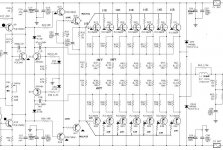
As for this project, i have builded before 9 years about 40 units to drive each one a special subwoofer. This was the Peavey UDH (obsoletted now) a tremendous band pass type subwoofer equiped with four 15" BW speakers of 350Wrms each one. These subwoofers was imposible to give their killing bass driven by class D or G or H amplifiers. I used each set with the low pass frequency at the electronic xover placed at 120Hz! This amplifier due to its ultra low output Z (you can see the 7 matched pairs of output devices) proved very effective. I will try to post a photo of the interior of one amplifier because all are in work this moment.
At this time, i am not busy furthermore with such type projects. Instead, in my new projects for home use, i replaced all transistors from input up to the VGS with Toshiba.
If someone wish to make a reffinement of this project, then i am available for any help.
This project proved very durable for 9 years of continuous operation under peak power conditions for 5 to 9 hours per day.
Regs
Fotios
- Status
- This old topic is closed. If you want to reopen this topic, contact a moderator using the "Report Post" button.
- Home
- Amplifiers
- Solid State
- A powerFULL amplifier named Dirty Harry