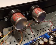
I thought you would ask that ") Inside the tube is a New Class D 5V regulator which has a skull piercing bright blue led. As I want to be able to see the green leds on the dddac main board, my make-do wooden case has a glass panel on top. The tube is there to protect my eyes. If you had expected a secret state-of-the-art hi-tech device I have to disappoint you.
Inside the tube is a New Class D 5V regulator which has a skull piercing bright blue led. As I want to be able to see the green leds on the dddac main board, my make-do wooden case has a glass panel on top. The tube is there to protect my eyes. If you had expected a secret state-of-the-art hi-tech device I have to disappoint you.
Inside the tube is a New Class D 5V regulator which has a skull piercing bright blue led. As I want to be able to see the green leds on the dddac main board, my make-do wooden case has a glass panel on top. The tube is there to protect my eyes. If you had expected a secret state-of-the-art hi-tech device I have to disappoint you.I have a question for the various PCM1794 experts here:
Looking at PCM1794 data sheet page 11, figure 19, it is well known that this DAC has fairly significant rising out of band noise - even though the dynamic range is very good in audio band.
Now - looking at the PCM1796 data sheet, page 13, figure 20, the out of band noise is much flatter all out to 100kHz but the dynamic range in audio band is less.
Does anyone know design wise, what would be the differences to cause this? These DAC's both share very similar advanced segment architecture.
Thanks and apologies for (slight) thread derailment... I thought this might also be interesting subject for 0 x OS DAC owners.
Terry
I have a question for the various PCM1794 experts here:
Looking at PCM1794 data sheet page 11, figure 19, it is well known that this DAC has fairly significant rising out of band noise - even though the dynamic range is very good in audio band.
Now - looking at the PCM1796 data sheet, page 13, figure 20, the out of band noise is much flatter all out to 100kHz but the dynamic range in audio band is less.
Does anyone know design wise, what would be the differences to cause this? These DAC's both share very similar advanced segment architecture.
Thanks and apologies for (slight) thread derailment... I thought this might also be interesting subject for 0 x OS DAC owners.
Terry
The datasheet pcm1794 graph is with 48kHz fs and the 1794 graph is 96kHz fs
also the measurement circuit id different - the 1796 has two additional HF filter poles
so basically the two datasheets are not apples and apples for this measurement
The datasheet pcm1794 graph is with 48kHz fs and the 1794 graph is 96kHz fs
also the measurement circuit id different - the 1796 has two additional HF filter poles
so basically the two datasheets are not apples and apples for this measurement
You are right (mostly) but there still seems more HF noise in 1794 comparatively speaking.
The 1796 has 1 more pole (3) and CF is 50kHz (usually -3dB)
The 1794 has 2 poles and CF is 162kHz.
Both FFT bins are same
Not sure what difference 48 vs 96 would make to noise floor - if anything I would have thought 48kHz would have less OOB noise.
Transposing the 50kHz filter on to 1794 there would still be a bump at 40kHz that the 1796 does not have.
Anyway, it was just an observation.
T
"Try 100 Ohm termination resistors."
No improvement with 100R resistors.
Last option: the 1/2 clock delay modification. Frankly I have no idea what this is, but if you tell me how to go about it, I think I can manage.
The delay of the I2S is required to get the DAC chip to work in NOS mode. You can read more about this on dddac.com. The red board implements the delay using a passive R-C circuit. The blue boards use an active circuit. The red board can be modified with the active circuit, but you need the right parts on a small add on PCB. There was a guy here on diyAudio selling those PCBs, but I don't know if he still does that. Maybe it's easier to replace the red board with a new blue board?
ok, so all ist fine in terms of the bias / analogue power...
Where next to look or check?
Cool, that was quick!Kali is working fine with the blue mainboard!
Where next to look or check?
it is some time now... what was the Problem again?
Last edited:
Mounting Cinemags
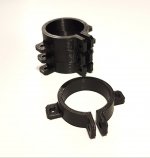
I struggled a little bit with how to mount a couple of Cinemags (in this case 15 / 15b without studs) neatly.
Looking at the forum images I'm not the only one, that's why I want to share my mounting method: a holder printed with a 3d printer by a colleague.
If you have a 3D printer or know someone, this is an easy and neat solution.
Marcel
Attachments
Nice solution using modern technology. When I built my First Watt F5 V3 monoblocks I just coudn’t use the cheap thin metal brackets that came with the Jensen input transformers I installed. I had some small pieces of 1” cherry so I used a Forster bit to drill a hole about 1/4” larger than the transformer partially through the wood. I then put some silicone in the bottom of the hole and embedded the transformers in it. Mounted the blocks to the bottom of the amp with 2 bolts.
3D printing is an ideal solution for his kind of low volume small part.
3D printing is an ideal solution for his kind of low volume small part.
The music is distorted
that is a bit short description.... help us help you by being more precise and descriptive what and when the issue is
is it harmonic distortion or "digital" distortion like crackles?
does it start immediately or after warm up ?
is it only at loud passages or also at low volume?
both at spdif and USB,
things like that....
pls download a 1kHz test tone somewhere, play it and use a simple multimeter to measure the AC voltage on all 4 output pins and post the result please
I have a power supply that will supply 4.5A. The tent boards use about 200ma each so 3.3 A was no problem.
I just stumbled over this 12 decker here (I used google translate to read it in English). They claim the 12 decker consumes 3.5A. Scaling this to 16 decks gets to the limit of your 4.5A supply. Hmmmm.
Oh, I am still looking for a second-hand blue mainboard. And I may also be interested in some additional DAC boards. Anyone?
Can you send me the link, I would like to see what they have done. When I was trying the 16 decks I measured the current and it was 3.35A and voltage at 12.5V with a music signal applied so there was no lack of power on my setup.
Can you send me the link, I would like to see what they have done. When I was trying the 16 decks I measured the current and it was 3.35A and voltage at 12.5V with a music signal applied so there was no lack of power on my setup.
Argh, sorry, forgot to insert the link. It's here: Een 12-deks DDDAC1794, Roon DSP en MQA
I am cleaning up my hobby room (it is spring after all)
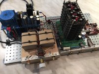
Would anyone be interested in this ? I used it for demonstrations, hence the simple build. Of course you can fit this in another chassis. It is with 8 of the "old" boards!
Of course 100% OK and it is a full system with the special DDDAC-Sowters Output - but as a 12 steps TVC version. (I use a 18 step version right now by the way)
So no need for a preamplifier, can go straight to the end amplifiers
Send me a PM if you are really interested - please no questions "how much" out of curiosity. Let's not waste each others time
Would anyone be interested in this ? I used it for demonstrations, hence the simple build. Of course you can fit this in another chassis. It is with 8 of the "old" boards!
Of course 100% OK and it is a full system with the special DDDAC-Sowters Output - but as a 12 steps TVC version. (I use a 18 step version right now by the way)
So no need for a preamplifier, can go straight to the end amplifiers
Send me a PM if you are really interested - please
no questions "how much" out of curiosity. Let's not waste each others time Attachments
Argh, sorry, forgot to insert the link. It's here: Een 12-deks DDDAC1794, Roon DSP en MQA
Thanks for the link, I will have a good read
- Home
- Source & Line
- Digital Line Level
- A NOS 192/24 DAC with the PCM1794 (and WaveIO USB input)