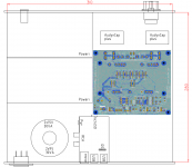
Enclosure layout with CAD
hi gwikse,
thanks for your detailed modeling work!
I am using SketchUp with your component in order to determine the dimensions and internal layout of the enclosure;
The model is done for now. Will update it and make it more accurate if there is enough interest or if I need it for my own project. Now on to the other modules
It can be found in the 3dwarehouse by searching for DDDac, NOS, DAC, PSU, gwikse, etc etc or if I am lucky this time; the link below.
https://3dwarehouse.sketchup.com/model.html?id=05c93d1a-be94-488c-8df2-52711bd68af1
hi gwikse,
thanks for your detailed modeling work!
I am using SketchUp with your component in order to determine the dimensions and internal layout of the enclosure;
An externally hosted image should be here but it was not working when we last tested it.
Nice to see it used. I had to put the project on hold, so I have not put in dimentions yet. Not sure when I will get the time and money to start it, so I might as well give you the model as it is right now (no measurements).
Here is the main part of the motherboard (missing the part that is broken off to be placed on the front panel) + a 4stack of the dac boards.
https://3dwarehouse.sketchup.com/model.html?id=c8cd2340-a27f-42e9-97a4-63eace297c06
Here is the main part of the motherboard (missing the part that is broken off to be placed on the front panel) + a 4stack of the dac boards.
https://3dwarehouse.sketchup.com/model.html?id=c8cd2340-a27f-42e9-97a4-63eace297c06
thanks gwikse... movin' on ")
BTW, power supply is still WIP, i guess? no bottom spacers, so i added them. actually, (SketchUp) components define precise dimensions for the layout!
it is not by chance that you have drawn output caps, right? anyway, thanks again!
An externally hosted image should be here but it was not working when we last tested it.
An externally hosted image should be here but it was not working when we last tested it.
BTW, power supply is still WIP, i guess? no bottom spacers, so i added them. actually, (SketchUp) components define precise dimensions for the layout!
it is not by chance that you have drawn output caps, right?
anyway, thanks again!I tidied some of my wires up this week and tried to make things a bit more proper and permanent, so it started like this

And this

Then

Closely followed by (mainboard reg output detached)

And (ignore the silly massive gold resistors, I guessed the spec wrong and had to dig in the spares temporarily)

With a few new data wires

And a bit of standoff jiggering


And I've made it all fit and I can (in theory) now close the lid(s) for the first time in about a year should the need arise...

Sounds pretty good too quite a step up from the level of detail I've heard from a dddac before. So that's without any of the dddac mainboard data signal processing, just a reclocked signal direct from the Cronus to as close to the DAC chips as is practical. The mainboard is only there to hold the i/v resistors for the moment.
And this
Then
Closely followed by (mainboard reg output detached)
And (ignore the silly massive gold resistors, I guessed the spec wrong and had to dig in the spares temporarily)
With a few new data wires
And a bit of standoff jiggering
And I've made it all fit and I can (in theory) now close the lid(s) for the first time in about a year should the need arise...
Sounds pretty good too
quite a step up from the level of detail I've heard from a dddac before. So that's without any of the dddac mainboard data signal processing, just a reclocked signal direct from the Cronus to as close to the DAC chips as is practical. The mainboard is only there to hold the i/v resistors for the moment.Here's my planned layout for DDDAC implementation with one DAC board (Tent shunt version). The source will be a Raspberry Pi 2 with Hifiberry DAC+ pro connected via I2S to DDDAC. The peace of paper represents the DAC-board as it is still on it's way to Finland.
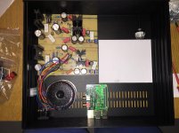
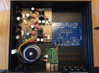
I've built the DDDAC power supplies by myself on a piece of perf-board and the two toroidal transformers are stacked on each other. The front plate is on top side and the rear panel is in the bottom of these pics. There will be selector switch in the front to choose from 4 outputs (Active monitors, headphone amp, two spares). Also a power switch will be placed on front panel.
I've built the DDDAC power supplies by myself on a piece of perf-board and the two toroidal transformers are stacked on each other. The front plate is on top side and the rear panel is in the bottom of these pics. There will be selector switch in the front to choose from 4 outputs (Active monitors, headphone amp, two spares). Also a power switch will be placed on front panel.
Attachments
Last edited:
Wohoo! The dac boards arrived today. It seems that my layout might actually work. I drilled the holes for Raspberry and bolted it to the base plate. Still need to make holes for Raspberry's USB/LAN connectors to back plate and for power switch/output selector to front plate.
Attachments
Last edited:
Most of the upgrades anyhowJames,
Looks like you have done every upgrade possible to your single board buffered DAC. IMO there is no need to stack DAC boards to get great sound. Nice looking chassis. I bet it sounds amazingly analog and musical too.
I need to look into the Cronus for my DDDAC.
I still really want to try with C0G SMD caps direct at the pins and maybe trial a couple of different voltage regs and I'd like to swap my Squaristor I/V resistors back in instead of the Z-foils to see if I can tune the sound to be a touch more tonally rich. But it doesn't sound so bad at the moment I would highly recommend the BBB>Hermes>Cronus route. I don't think anything better exists for that kind of money and with that depth of software support. But then I do recognise that I am at the far end of the modification trail and I love a puzzle rather than the quick and easy route
Last edited:
Nice dac James
I have one question about the I/V resistors. Today I recieved my AN Tantalum 2w's from Hifi-collective UK. Since I have an dac with 8 boards i ordered four 18R. I've been using 8 stock resistors 34R in paralell to land 17R. BUT the AN resistors choke my dac, with the volum on max, there is hardly any sound. It's very low.
Have I misunderstod something ? Should it not be ok with four 18R on 8 deck ?
Forgot to mention that 4 of the boards are the new ones which draw twice the current, maybe this is the reason ?
When I put back the 8 dale 34R, everything is fine.
Sounds right, I'm assuming you've checked the actual values of the new parts with a meter?Nice dac James
I have one question about the I/V resistors. Today I recieved my AN Tantalum 2w's from Hifi-collective UK. Since I have an dac with 8 boards i ordered four 18R. I've been using 8 stock resistors 34R in paralell to land 17R. BUT the AN resistors choke my dac, with the volum on max, there is hardly any sound. It's very low.
Have I misunderstod something ? Should it not be ok with four 18R on 8 deck ?
Forgot to mention that 4 of the boards are the new ones which draw twice the current, maybe this is the reason ?
When I put back the 8 dale 34R, everything is fine.
My guess is the position of your 4 x I/V resistors. Each channel on the mainboard you have 2 pairs of places to put the resistors, ra+rb and then ra+rb again. With 4 resistors for each channel you have no choice and use all holes. With 2 per side, you have options and some of those are wrong.
You must have 1 resistor in each pair. Otherwise you have no I/V for one half and only half volume for the other half, as it will see 9ohms.
It's easy to see which are linked in the datasheet

Last edited:
Yes, that's what I meanThe resistors measure 17.94 ohm on my fluke.
Are you realy shure about the datasheet James ?
The 8 Ra and Rb holes on one side, is actually 4 since they are connected to each others

If we put some numbers it's easier to explain.
So resistor positions 1 & 2 will connect pos to common and positions 3 & 4 will connect neg to common.
If you have 4 resistor positions and 2 resistors, you have 6 possible places to put them:
1&2, 1&3, 1&4, 2&3, 2&4, 3&4
4 of these 6 choices are fine, because you will still have 1 resistor on pos and 1 in neg, but if you choose positions 1&2 or 3&4 then you only have resistors on on half and they are paralleled so they will half in their value.
If you place 4 resistors. Like 8 decks with 18 Ohm resistors, you must fill the four Ra positions
If (for what ever reason) you decide to use a combined resistor, like 68 and 22 Ohm to get close to 17 (just an example !!!) you put like the 68 on the Ra positions and the 22 on the Rb positions
If (for what ever reason) you decide to use a combined resistor, like 68 and 22 Ohm to get close to 17 (just an example !!!) you put like the 68 on the Ra positions and the 22 on the Rb positions
Hello Guys - I have been a very happy user of the DDDAC 1794 from India. I started using the DDDAC around 4 years ago with one board configuration. I use the old red main board.
Over the years, I slowly upgraded the DAC and have the following configuration with changes :
- Red main board
- 4 deck version
- Using Russian PIO capacitors on the output side.
- Using 33 ohm Rload resistors on both channels.
- Got 1.2V DC output voltage on both channels.
- was noticing some distortion from the left channel which could have been quantization noise. Took a lot of advice from Doede and changed the regulator from LF33 to LF50 and introduced 22nf filter caps across pos & neg of the top most DAC deck. LF50 did not introduce any change but 22nf did mellow the sound.
- Increased the 22nf to 44nf and the DAC became smoother sounding but it took slight openness of the sound away. But it felt like a good compromise.
- Mine is a capacitor coupled output. I shifted from the kit electrolytic caps to Russian PIO capacitors as I liked that sound signature better. But after introducing 44nf filter capacitors on top, I wanted to go back to the electorlytic caps that Doede supplied as these are slightly open sounding.
Problem :
When I put the original capacitors back into the output path, these were just kept inside the DAC case but were not tied/fixed in their position.
When audio was playing today, I just wanted to see that these capacitors should not be touching each other. So with my finger I tried to separate these. In this process, I am not sure what happened but one leg of the capacitor touched maybe the main Red board maybe at the 12V supply area or one of the DAC decks, and I heard a slight pop sound and the right channel stopped giving out any sound. I immediately powered off the DAC and checked the connections. All seemed fine. I went back to the PIO capacitors and then started to hear very low volume signal from the right channel. Tried switching off and on the DAC multiple times but it did not help.
After nothing seemed to work, I started measuring things with my meter. 12V & 5V power supplies are fine. output capacitors have correct value. Bleeder resistors on the RCA output side are also correct in their value.
Now issue is that the Rload resistors on the left channel, both correctly measure 34ohms each. When I move to the right channel, one of the resistor measures 34ohms but the other measures only 2.6ohms.
Output DC voltage on the left channel has now turned to 2.6V and the Voltage on the right channel is 167mV. It feels as if it has gone into a balanced output mode and has doubled the left channel voltage and reduced right side to almost 0V.
Clearly shows why I am hearing so low output on the right channel. Also, to test the bad resistor, I disconnected that resistor and out of circuit it correctly measures 34ohms but when connected back, it measured 2.6ohms again.
I am a noob who has probably done a short somewhere in the circuit. I will be keen on your knowledge to point out what I can do to rectify this issue. Please help.
Very strange.....after soldering in the An tantalums, still almost no sound.
With 8 dale 34R everything is ok, but with 4 AN tantalums 18R not ok.
The 4 tantalums are soldered to Ra-Ra on both channels.
I was hoping to use the tantalums since so many like them, but what can be the wrong here ? The voltage between common -pos and neg is 8v. No dc pos-neg.
I have noticed a volt difference on input with load. 8 dale 34R, measure 9vdc. The tantalums, 10.5 vdc.
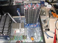
Your photo should come with a vertigo warningTent shunt boards now on top of the stack.
I hope to test later this week.
Should sound rather nice I would think
- Home
- Source & Line
- Digital Line Level
- A NOS 192/24 DAC with the PCM1794 (and WaveIO USB input)