I know it's a bit off topic. Sorry to disturb.
For those low-current, 0V nominal, zero IV input impedance DACS like PCM63, PCM1704, AD1865, ...., I personally think that the Hawksford IV circuit is hard to beat. It works very similar to the Pass D1, except that it allows current amplification. And it does not have output coupling caps.
Here is my attempt for one version using the LU1014D power JFET in triode mode and a current gain of 12 (i.e. equal to paralleling 12 DAC chips together).
http://www.diyaudio.com/forums/digital-source/168093-hawksford-discrete-iv-twist.html
LU1014 in triode mode :
http://www.diyaudio.com/forums/pass...urce-follower-configurations.html#post1595867
No time to build yet, but WILL do eventually.
Patrick
Last edited:
Hi Guys,
Sorry for the 2 week absence, I was on vacation, and then had a lot of work to catch up on which didn't leave much time for anything else.
I've also been busy installing the 50 drivers in my latest line-array project, which is taking far more time than I was hoping.
Before I left, I measured the circuit as built on Pierre's PCB with a very closely matched pair of fets (for both Vgs and TC). I'm now riding the measurement limit of the Audio Precision at -112dB THD+N. I'm fairly sure the system is actually better than that, but even if I loop the AP straight from generator output to analog input, the best I get is -112dB with a 2VRMS signal. I would say that the circuit itself is definitely finalized, and I'm more than thrilled with that level of performance. Even the best op-amp based circuits would struggle to perform that well, and this does it with no feedback, and only a single device / gain stage.
qusp:
I'll snap a few pictures and post them tomorrow. I've got both channels done, and I've listened to the whole thing using a lab supply. The next step will be to make a regulated +/-50V supply to go along with it. When I'm happy with everything, and done some tweaking of the PSU, then I'll finally make the final PCB.
I know it has been a long time coming, but at least when it's done, it'll be perfect. There's nothing worse than making a PCB that isn't everything you wanted it to be.
Samoloko:
Lowering the resistor values does indeed lower the gain, and there's nothing you can do to change that basic fact, other than adding another gain stage. I would say that the sweet spot is really the lowest gain you can tolerate, which in my case is 2VRMS at 0dBFS. If you can live with 1VRMS, then by all means, you can lower the resistors values and get even more current through the fets for a given voltage level.
Calvin:
The voltage mode measurements were taken with only a pair of 750 ohm resistors on each output to ground. I soldered the resistors directly to the XLR jack, and ran 2" leads from the DAC output to the XLR jack. I verified the setup several times since I was quite surprised by the poor results.
The generator is the AP built in digital generator which gives -148dB THD+N when looped back to the digital input at 24 bit, 192kHz. The limits of the analog analyzer is about -112dB THD+N, so that's not what was causing the poor measurements.
Realistically, the DAC isn't designed to be run in "Voltage Mode" and for all I know, they might have a very specific circuit that qualifies as "Voltage Mode". What I can tell you though, is that performance into a pair or resistors isn't good, and doesn't come anywhere close to the number on the datasheet at 0dBFS.
If someone else here has measured this and gotten better results, let me know what you did, and I'll try it again.
Cheers,
Owen
Hi Guys,
Sorry for the 2 week absence, I was on vacation, and then had a lot of work to catch up on which didn't leave much time for anything else.
I've also been busy installing the 50 drivers in my latest line-array project, which is taking far more time than I was hoping.
Before I left, I measured the circuit as built on Pierre's PCB with a very closely matched pair of fets (for both Vgs and TC). I'm now riding the measurement limit of the Audio Precision at -112dB THD+N. I'm fairly sure the system is actually better than that, but even if I loop the AP straight from generator output to analog input, the best I get is -112dB with a 2VRMS signal. I would say that the circuit itself is definitely finalized, and I'm more than thrilled with that level of performance. Even the best op-amp based circuits would struggle to perform that well, and this does it with no feedback, and only a single device / gain stage.
qusp:
I'll snap a few pictures and post them tomorrow. I've got both channels done, and I've listened to the whole thing using a lab supply. The next step will be to make a regulated +/-50V supply to go along with it. When I'm happy with everything, and done some tweaking of the PSU, then I'll finally make the final PCB.
I know it has been a long time coming, but at least when it's done, it'll be perfect. There's nothing worse than making a PCB that isn't everything you wanted it to be.
hey Opc, thats excellent numbers mate and if its even better (which seems likely) then sounds like we found a winner
") so will you be providing PCBs for the regulated PSU to match as well? I have coffins minigold regs that will go up to 50v, but I dont have much else as I usually dont deal with such voltage, not being into tubes and being more into headphones than speakers. Most of mine top out at +/-35v, but yeah the minigold is quite good and will handle considerably more. I also have some of peranders RFB03 discrete rectifier PCBs to provide a nice raw DC supply from a center tapped 50-0-50 2A transformer (well actually the same iron has all the other voltages I need for this dac as well, custom wound by Richard Sumner (sumR)
so will you be providing PCBs for the regulated PSU to match as well? I have coffins minigold regs that will go up to 50v, but I dont have much else as I usually dont deal with such voltage, not being into tubes and being more into headphones than speakers. Most of mine top out at +/-35v, but yeah the minigold is quite good and will handle considerably more. I also have some of peranders RFB03 discrete rectifier PCBs to provide a nice raw DC supply from a center tapped 50-0-50 2A transformer (well actually the same iron has all the other voltages I need for this dac as well, custom wound by Richard Sumner (sumR)so yeah if you can post those pics of the setup you got those numbers with thats well good enough for me to use pierre's PCB till you are finished yours, so theres no rush from me mate, happy for you to be perfectly satisfied youve made it as good as you want it to be.
cheers, hope you had a nice break, i'm jealous
Hi,
thanks Owen. The ESS puts out tiny currents (what a weak whimp....nothing to drag a Tool Time Fan off behind the oven , howhowhow *lol*). Still though did You consider that 750Ohms could be so high that internal protection diodes start conducting -> hence increased THD-values? I don´t know if the ESS features protection diodes on its outputs but the BB/TI current steering DACs like the PCM179x surely do.
As I understand the poor information from ESS, voltage mode and current mode differ only in the topology of the connected circuit. The outputs have an iimpedance value of 200Ohms, which is neither fish nor flesh. Too low for a decent current source and too high for a true voltage source. ESS might call this a feature ..... at the moment I´d call it a bug. ;-(
jauu
Calvin
Hi Calvin,
You made a good point with your internal protection diode idea which forced me to go back and take a second look at the datasheet to double check the stated voltage values at the output.
While doing so, I noticed that the stated maximum output voltage is 3.05Vpp, which I was reading as a peak value. That means in voltage mode, the most you can get out of the DAC is 1VRMS which means I was running too high an output voltage when I measured the resistor only configuration.
I'll re-measure with a lesser value of resistance, in this case just enough to get 1VRMS output, and I'll report back with my findings. I'll start with 80 ohms and go from there.
Keep in mind that this is the differential output voltage value, so for anyone out there using this thing with a resistor, make sure you double check your setup. If you're running differentially, you should have no more than 1VRMS output at 0dbFS, and if you're running SE, then it should be less than 0.5VRMS.
Cheers,
Owen
Hi qusp,
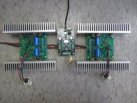
As requested I've attached a photo of the DAC as I have it set up on Pierre's PCB's. There are a few jumpers, and the mosfets needed some lead bending to fit in the TO-220 outlines, but it all went together pretty well.
It's not the most portable setup, but it's the closest I've come to a finished design so far.
The final PCB will indeed have the power supplies built right in for the +/- 50V (adjustable if you want lower). I'm also going to toss one in for the DAC itself (5.5V), but using it/populating it will be optional. I kinda want an all-in-one solution that you can just drop the Buffalo II onto, and be finished. I will, however, provide for external power supply tie points for those wishing to use something fancier than an LM317/337.
Cheers,
Owen
Attachments
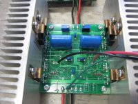
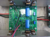
Hi mate, wow, now thats a mans dac IV so no changes to the values? yeah the FQA actually fit quite well with some coercing. pots are 100K yes? so FQR, 100K pots 200/400 and what BOM is the rest following?? the small blue caps are?? the large blue caps are?? and is there any jumpers under the board? oh and where did you get those clips that seem to be for more evenly distributing the heat from the fets and Rs from?
so no changes to the values? yeah the FQA actually fit quite well with some coercing. pots are 100K yes? so FQR, 100K pots 200/400 and what BOM is the rest following?? the small blue caps are?? the large blue caps are?? and is there any jumpers under the board? oh and where did you get those clips that seem to be for more evenly distributing the heat from the fets and Rs from?question for simulation in ltspice
Hi.
just playing around with some simulations. I have an buffalo DAC (ES9008)
The data-sheet is not really clear to me. The max differential output-current is 4.2mA and the DC offset is 1.65V correct ? For one channel half of current or ?
thx
Hi.
just playing around with some simulations. I have an buffalo DAC (ES9008)
The data-sheet is not really clear to me. The max differential output-current is 4.2mA and the DC offset is 1.65V correct ? For one channel half of current or ?
thx
Attachments
![Screenshot-LTspice IV - [IV_Stage6.asc].png](/community/data/attachments/151/151143-224574e54826b624f279c629dad7b084.jpg)
Owen, can you please reply with the values for the caps you have in those pics? what scema are you using for that, it seems different to the no cap one. I have the resistors (the power ones, sorted) I know what fets, but need to know the cap values for hirez and the small through hole ones you have used there.
can you point me to the schema if you already posted that one. has been a few and without knowing what those caps are its difficult to tell if you made any changes for the higher voltage and using the PCB from pierre. I need to build it up this weekend as the sydney headfi meet is coming up next week and i'm running out of time. i'll be right once I know those, its straight forward to build and I have every possible combination of values pretty much
thanks mate
i'm assuming 0.01uf, but is that really a 22uf film the big blue ones? and the small resistors are? soldering iron at the ready!! I have like 10 days to assemble and test the ackodac, most parts arrived today, but if I cant get that done, I would at least like to install the mosfet IV in my buffalo II for the meet.
Hi qusp,
I see you're under the gun! I know the feeling... we had a meet here in Ottawa last week and I spent all night trying to finish up a pair of line arrays to bring along with me. I even enlisted my wife to help with the gaskets and driver installation! I got them done, but just barely.
I've attached a PDF with the final schematic, and all the values that were used to get everything just right. This is exactly the way I have Pierre's PCB's setup right now. You can use this schematic at a variety of of voltages, by simply adjusting the value of the resistor feeding the gate of the fets. In this schematic you're looking at R16, 17, 24, 27 with a value of 30k9 which works perfectly for around 50V rails. If you drop down to say 18V rails, then you'll want something more like 10k in place of the 30k9. All other values stay the same.
For the output coupling caps, I would suggest going larger than the 6.8uF listed on the schematic. You can use anything from 4.7uF to well over 100uF, but you'll probably get some low frequency roll-off with values less than 10uF, depending on the input impedance of the following stage. In my case, I know that the next stage has an impedance of 22k, which gets me a LF corner frequency of 1Hz.
Here are the parts I used:
200R = Caddock MP930
400R = Ohmite TN15P400RFE (Thin Film)
FET = FQA32N20C
10uF Caps = TDK 10uF ceramic 50V Y5V (I like to live on the edge)
Output caps = Epcos 6.8uF Polyester
Other resistors = 1% metal film
For the four caps that set the HF filter, I still don't have the correct values, but I've been using the DAC without them and I can't hear or measure a problem with that setup. If you're running the DAC at 96 or 192kHz then I'd suggest leaving them out completely. If you're always running at 44.1 then it might be beneficial to have them, but certainly not necessary. I'll get the values sorted out soon for those who really want them.
Let me know if you have any problems with your build, and I'll be sure to help out.
Cheers,
Owen
Attachments
Hi Guys,
Just thought I'd let you all know that I finally got around to testing the IRF610 after Pierre kindly supplied me with a few at the Ottawa DIY meet last weekend.
For the same values as the other fets (Vds=25V Id=130mA) the transconductance is 0.360S (average of two devices tested).
It's neither good nor bad, so if you have it, you can use it, but you'll get better results with the suggested FQA32N20C. As for the sound, you'll have to try it yourself to find that out.
Cheers,
Owen
also owen, I dont have a pot on my QRV08 dual mono headamps, which are in the same case as headphone amp and buffer/line driver (defeat-able) i'm using the sabres internal digital pot and the headamps have a buffer (4 discrete diamond buffers a channel in my case) with or without gain as the first stage. so the input impedance is massively high, I could probably get away with 0.1uf, on the input there is an optional DC removal 0.1uf SMD PPS film cap, which since the amps have servos and output offset will be very low if I leave a cap on the output of the D1, I could omit the cap, then there is a 470k R on the way to the regulator and another 100k to ground directly after (pull up, pul down) and the effective input impedance of the amp is 1MO haha, so either way the cap value can be very low indeed. only reason to think about a larger cap there would be to allow for the option of using the dac without the headamps inline (IE not using its unity gain mode as a buffer by installing a switch or separate set of outputs), but i will see how it all sounds before I make those sort of tweaks.
so really I could look at buying another 2 x mundorf silver in oil 0.68uf or another 2 x VCAP CUTF 0.1uf to go with the 2 I have and using those. so I dont think I have to worry about 10uf, I will have another look at the input impedance of my active monitors, but I think if I did work it so the QRV08s arent in the line out, I would work out some sort of switching arangement, or simply put the output caps inline with the output wiring connected directly to the XLRs
so really I could look at buying another 2 x mundorf silver in oil 0.68uf or another 2 x VCAP CUTF 0.1uf to go with the 2 I have and using those
. so I dont think I have to worry about 10uf, I will have another look at the input impedance of my active monitors, but I think if I did work it so the QRV08s arent in the line out, I would work out some sort of switching arangement, or simply put the output caps inline with the output wiring connected directly to the XLRsBalanced to unbalanced
How can I connect this D1 circuit to the unbalanced input of my preamplifier?
Using a transformer do I need a center tap on the primary to be connected to ground? Which transformer would be best suited? And are the output capacitors necessary?
Regards.
Paul.
How can I connect this D1 circuit to the unbalanced input of my preamplifier?
Using a transformer do I need a center tap on the primary to be connected to ground? Which transformer would be best suited? And are the output capacitors necessary?
Regards.
Paul.
Hi Paul,
You can just use a 1:1 transformer, no need for center taps. If you do go that route, then you shouldn't need to use any coupling caps since both outputs are at the same potential in a well adjusted circuit, and that should mean no DC across the transformer.
I might actually try it out with a small signal transformer I have kicking around here, and I'll let you know how it works. There seems to be a lot of people interested in using SE output.
Cheers,
Owen
- Status
- This old topic is closed. If you want to reopen this topic, contact a moderator using the "Report Post" button.
- Home
- Source & Line
- Digital Line Level
- A New Take on the Classic Pass Labs D1 with an ESS Dac