Pulse mode curve capturing might have its limitations.
As the curves are taken at a relatively low frequency interval time is quite high . Meaning that a tube has enough time to regenerate its electron cloud between intervals.
If you where to capture curves in real static DC conditions. I think the curves would hardly look alike
The curves could be a good indication of a worn tube. As a tube whit good emission could sustain higher anode current . Over longer periods of time . (seconds instead of milliseconds )
Please correct me if im incorrect. I'm in a learning curve
v4lve
I think your concern might be overblown, please refer to the following link that showed pulse measurement works just fine, while the circuit, sampling period, software for the experiment were different from Michael's version, the conclusion should still hold. Just my 2c...
")
The uTracer, a miniature Tube Curve Tracer / Tester.
Jaz
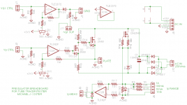
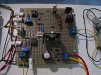
Here is the programmable regulator (pregulator) on my breadboard. It has a 0 => 300V floating plate regulator with return path current sensing, and a simple level-shifted op amp for the -28V => 0 grid supply.
Q3 CCS and 15V zener diode are to generate a negative tail voltage for the common source amplifier Q2. THe ground reference is returned through current sensing resistor R1.
All the operating current for the HV circuit flows between the supply rails and only the tube anode current and the anode voltage divider R9 (1M) current go through the sensing resistor to ground. The cathode of the tube is grounded. The voltage divider current (microamperes) can easily be calculated from the anode voltage and subtracted from the measurement to obtain the tube current only. This is particularly important in the 1mA range.
The floating anode supply consists of a 10VA toroid, FWB, and 10/450 capacitor. The capacitor holds enough charge for the 1-100mA ranges. At 100mA plate current the droop is 10V in one millisecond. For the 1A range a larger cap may be needed, depending on the plate supply voltage margin and the measurement cycle time. The regulator holds the plate voltage constant as the capacitor voltage droops as long as there is some voltage headroom.
I had 200 KHz oscillation until I switched from a TLE2072 (high performance TL072) to a TL062 in the plate regulator. I think some high performance op amps are barely unity-gain stable and if you add an external gain loop of less than one in the feedback path they go unstable with no way to compensate.
I'm putting a project page together for this and will post a link when it's up. I think I'm going to go right to PCB design of a bipolar-capable regulator so I can start some real tube tracing.
Oops D8 is 14V...
Attachments
Last edited:
Hi Michael
Any progress with this great project?
Yes, I'm designing a bipolar capable electrode driver PCB with programmable offset to -200V plus a low voltage driver using a power op amp. I'm also going to build a 1500V plate driver so I can test transmitting tubes.
I'm currently in the middle of moving my house, lab, workshop, and studio all at once so will have limited lab time over the next few weeks.
The idea of measuring points randomly or in a high/low sequence sounds good but there is a practical issue. The plate current is not known until the plate voltage is applied. For triodes with low internal resistance, it's not practical to try to apply the entire range of plate voltage at low or positive grid voltage, for reasons of cathode saturation. It's also really easy to program a pseudo plate resistor if the points for each plate curve are measured in sequence. That gives the nice lined up endpoints. Also there really is no issue with average dissipation but I do worry about cathode damage with high current pulses.
I'll have time to write things up a little better and create a project page on my website soon.
Cheers,
Michael
- Status
- Not open for further replies.
- Home
- Design & Build
- Equipment & Tools
- A micro-programmable tube tracer/tester