Wow! It's precisely because of machines like that that I'm building this. I'm not doing anything nearly that ambitious. 80 euros just for the plans  I applaud the effort but I'm too lazy for all that.
No, this is all going to be open source and open hardware. It's not trying to be everything to everyone at any cost. It's super simple and programmable and ultimately can do everything "tinge of red" can do for a fraction of the cost.
What I realized is that an entirely new approach would yield a machine orders of magnitude simpler than that one and it's ilk, and won't be limited by hardwired logic circuits.
Maybe this tracer won't be as automated and turnkey, but I'm targeting tube DIY builders and hobbyists like myself. It's useful as much as a discovery tool as well as for testing and matching tubes for replacement, etc.
Cheers,
Michael
I applaud the effort but I'm too lazy for all that.No, this is all going to be open source and open hardware. It's not trying to be everything to everyone at any cost. It's super simple and programmable and ultimately can do everything "tinge of red" can do for a fraction of the cost.
What I realized is that an entirely new approach would yield a machine orders of magnitude simpler than that one and it's ilk, and won't be limited by hardwired logic circuits.
Maybe this tracer won't be as automated and turnkey, but I'm targeting tube DIY builders and hobbyists like myself. It's useful as much as a discovery tool as well as for testing and matching tubes for replacement, etc.
Cheers,
Michael
Well, it`s not just schematics and a BOM but a complete set of instructions including: programmed PIC microcontroller, software (however German only, I guess), USB driver, PCB Layouts (Gerber files), tube database etc. etc. (the special toroidal transformer with multiple secondary windings can be bought from the designer).80 euros just for the plans
Considering the complexity of this ambiguous project it seems a fair price to me and certainly worth it for someone who doesn`t have the knowledge and skills required to DIY something like this from scratch (like me).
Yeh mee too I'm afraid. I don't want to pay extra for ambition. But I do so like the pun-o-matic translator RoeTest = tinge of red 
Seriously, this will be for DIYers who just want to build something also (once it's farther along) at a much lower cost of entry and much more hackable. But then I'm not trying to recover an investment.
Cheers,
Michael
Seriously, this will be for DIYers who just want to build something also (once it's farther along) at a much lower cost of entry and much more hackable. But then I'm not trying to recover an investment.
Cheers,
Michael
Last edited:
Wow! It's precisely because of machines like that that I'm building this. I'm not doing anything nearly that ambitious. 80 euros just for the plans
l
You are right. Even if he only charged $1, the fact that plans are not openly published makes them useless for this kind of project. The plan I think here is a device that can be widely replicated and then one hopes some creative software will be written for it.
I'm working on pretty much the exact same thing, an Arduino controlled tube tracer and then found this thread. My goal is an even simpler design for what is being discussed here that could be built on perf boards and at low cost.
My thinking is that cost is not so much an issue as complexity. I want the smallest BOM possible.
I vote for your design, let's keep it simple and at a DIY level where most people can go build the tracer.No, this is all going to be open source and open hardware. It's not trying to be everything to everyone at any cost. It's super simple and programmable and ultimately can do everything "tinge of red" can do for a fraction of the cost.
A lot of what I see in that design has to do with making it support every tube ever made through a universal interface to adapter boards. That certainly adds complexity.
So one issue I see is how to interface the basic electronics which generate/control the four electrical elements (Anode, Screen, Grid, Cathode) to the physical tube sockets.
My current tester uses an octal socket on the base unit with plug in assemblies to adapt to the sockets I need, including one with flying leads for configuration. Nice but not mechanically sound, since it relies on the socket/plug for mechanical support.
This is what I used -- mini banana jacks/plugs:
An externally hosted image should be here but it was not working when we last tested it.
This might provide some ideas:
http://www.diyaudio.com/forums/group-buys/206794-gb-diy-curve-tracer-pc.html
http://www.diyaudio.com/forums/group-buys/206794-gb-diy-curve-tracer-pc.html
Specification
Here is a brief specification, updated block diagram, and HV regulator schematic. This is pretty much the state of the design as I build the first prototype.
Cheers,
Michael
----------------------------------------------------
Micro-programmed tube tester/tracer
Functional Specification
What is it?
A piece of test equipment used to measure the characteristics of vacuum tubes.
The tester is AC line powered and attaches to a PC via USB or Ethernet.
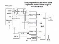
Internally the tester consists of a microcontroller and a set of programmable power supplies (see the attached block diagram) which apply test voltages to the electrodes of the tube being tested, and which measure the resulting inter-electrode currents.
The tester sends measurement data back to the PC for analysis and plotting. Simple functions can be implemented on the tester itself as needed e.g inter-electrode short circuit checking.
Who is this for?
The first iteration will be targeted at users with a good level of technical sophistication; Engineers, DIY amp builders, radio technicians, etc.
Initial uses:
- Data sheet parameter verification
- Tube characterization
- Matching
- Research, exploration and discovery
The platform should provide for functional enhancements in future versions:
- Plug and play testing with a database of thousands of tubes and go-no go parameters
- Relay configured socket modules
- Heater/cathode insulation testing
- Heater current verification
- Physical modeling for Spice -- Spice communicates with the tester and submits test points while evaluating the model
The rest of the specification refers to the initial deployment set of modules and software
Operational characteristics:
Test modes:
- Plate curves for diode, triode, tetrode, pentode
- u, rp, gm curves and point measurements
- screen grid (g2) curves
- curves with g1 and g2 modulated together e.g. ultralinear at various ratios, triode mode
- g3 manual bias setting
Test parameter range:
g1:
-200V to +100V, -20V to +10V ranges, (300mV, 30mV steps)
200mA drive capability
1mA, 10mA, 100mA, 1A current measurement ranges
g2:
0 to +300V, 0 to +600V (300mV, 600mV steps)
1A drive capability
1mA, 10mA, 100mA, 1A current measurement ranges
g3:
0 to -30V manual setting
plate:
0 to +300V, 0 to +600V (300mV, 600mV steps)
1A drive capability
1mA, 10mA, 100mA, 1A current measurement ranges
PC interface:
PC sends parameters to the microcontroller to set up and start the test.
The microcontroller then sequences through the test steps and outputs the test data in CSV format to the PC
After receiving all the data points, the PC then produces graphs, charts, tables, etc
Measurement:
The system will perform pulsed measurements, where all element voltages will be first set to baseline conditions, then measurements will be made by applying test voltages to all electrodes simultaneously, then after a settling time, sampling the electrode voltages and interelectrode currents, after which the electrode voltages are returned to baseline conditions.
In this way the average dissipation of the tube can be controlled by controlling the duty cycle of the measurement pulse. The tester will send CSV data to the PC after each measurement interval and add additional delay as necessary to limit the average dissipation during measurement. Pulse current and pulse peak power will be limited by tracking in software during measurement.
The following test parameters for a plate curve measurement example will be set using the PC application and sent to the microcontroller:
g1_start_V
g1_stop_V
g1_step_V
g2_start_V
g2_stop_V
g2_step_V
plate_start_V
plate_stop_V
plate_step_V
cathode_current_limit
plate_VI_limit
Code in the microcontroller performs the following to generate a set of plate curves and output to the PC:
// start plate curve set:
for (Vg1_out=g1_start_V; Vg1_out <= g1_stop_V; Vg1_out += Vg1_step_V) {
for (Vp_out=plate_start_V; Vp_out <= plate_stop_V; Vp_out += plate_step_V) {
// preload the DAC registers with the output values for the next measurement point
DAC_Vg2_set(g2_start_V);
DAC_Vp_set(Vp_out);
DAC_Vg1_set(Vg1_out);
// pulse the DAC /LDAC line to energize the DUT electrodes
DAC_LDAC(LDAC_PULSE_TIME);
// wait a bit for the electrode voltages to stabilize
delay(settling_time);
// read out the electrode voltages and currents.
// the timing for analogRead is 110 uS by default in the Arduino library
Ip = analogRead(Ip_ADC_pin);
Vp = analogRead(Vp_ADC_pin);
Ig1 = analogRead(Ig1_ADC_pin);
Vg1 = analogRead(Vg1_ADC_pin);
Ig2 = analogRead(Ig2_ADC_pin);
Vg2 = analogRead(Vg2_ADC_pin);
// now de-energize the electrodes
DAC_CLEAR(CLR_PULSE_TIME);
// send this point data to the PC
output_to_PC(Ip, VP, Ig2, Vg2, Ig1, Vg1);
// end this Vg trace if we have reached a measurement limit
if (Vp * Ip >= plate_VI_limit || Ip + Ig1 + Ig1 >= cathode_current_limit) break;
}
}
Hardware for initial embodiment:
Microcontroller:
An Arduino Mega 2560 will be used for the initial prototype and reference design.
Arduino doesn't provide true analog outputs (only PWM is on-board) but has good support for serial I/O.
The AD7808 will be used to provide synchronized analog outputs to control the electrode voltages during testing. An Arduino I/O Shield will be constructed to carry the AD7808 and provide I/O connectors to the high voltage programmable regulator modules.
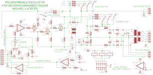
High Voltage Programmable Regulator modules:
Electrode voltages are driven by a set of programmable regulators, one for each electrode (plate, g2, g1). A control voltage from the D/A converter is scaled to either unipolar (0-600V for g2and plate) or bipolar output (-200V to +100V for g1). Each programmable regulator module carries it's own power supply including a small transformer and rectifier, energy storage capacitors, and voltage and current sensing circuits with protection.
The energy storage capacitors are sufficient to provide the rated electrode voltage from the regulator long enough to make a measurement (typically less than 1mS). The power supply is sufficient to charge the capacitor between measurement cycles ( ~ 1 to 10 mS ). For high current measurements, the measurement cycle time may be increased to allow the capacitor to fully recharge between measurements.
System enclosure:
The initial prototype will consist of a metal enclosure containing the Arduino and D/A shield, three programmable power supplies, small SMPS for logic and analog circuits, and the following external controls and interfaces:
Rear panel:
Fused switched AC input module
USB interface for connection to PC
External heater supply input
Top panel:
Octal DUT socket wired for EL34
Test plugs for rerouting DUT pins and add-on socket adapters
Front panel:
Power switch
Power indicator
g1 current range selector (1mA, 10mA, 100mA, 1A)
g1 voltage range selector (-20V to +10V, -200V to +100V)
g2 current range selector (1mA, 10mA, 100mA, 1A)
plate current range selector (1mA, 10mA, 100mA, 1A)
Heater voltage selector (2.5V, 5V, 6.3V, 12.6V, EXT)
g3 voltage control (0 to -30V)
Here is a brief specification, updated block diagram, and HV regulator schematic. This is pretty much the state of the design as I build the first prototype.
Cheers,
Michael
----------------------------------------------------
Micro-programmed tube tester/tracer
Functional Specification
What is it?
A piece of test equipment used to measure the characteristics of vacuum tubes.
The tester is AC line powered and attaches to a PC via USB or Ethernet.
Internally the tester consists of a microcontroller and a set of programmable power supplies (see the attached block diagram) which apply test voltages to the electrodes of the tube being tested, and which measure the resulting inter-electrode currents.
The tester sends measurement data back to the PC for analysis and plotting. Simple functions can be implemented on the tester itself as needed e.g inter-electrode short circuit checking.
Who is this for?
The first iteration will be targeted at users with a good level of technical sophistication; Engineers, DIY amp builders, radio technicians, etc.
Initial uses:
- Data sheet parameter verification
- Tube characterization
- Matching
- Research, exploration and discovery
The platform should provide for functional enhancements in future versions:
- Plug and play testing with a database of thousands of tubes and go-no go parameters
- Relay configured socket modules
- Heater/cathode insulation testing
- Heater current verification
- Physical modeling for Spice -- Spice communicates with the tester and submits test points while evaluating the model
The rest of the specification refers to the initial deployment set of modules and software
Operational characteristics:
Test modes:
- Plate curves for diode, triode, tetrode, pentode
- u, rp, gm curves and point measurements
- screen grid (g2) curves
- curves with g1 and g2 modulated together e.g. ultralinear at various ratios, triode mode
- g3 manual bias setting
Test parameter range:
g1:
-200V to +100V, -20V to +10V ranges, (300mV, 30mV steps)
200mA drive capability
1mA, 10mA, 100mA, 1A current measurement ranges
g2:
0 to +300V, 0 to +600V (300mV, 600mV steps)
1A drive capability
1mA, 10mA, 100mA, 1A current measurement ranges
g3:
0 to -30V manual setting
plate:
0 to +300V, 0 to +600V (300mV, 600mV steps)
1A drive capability
1mA, 10mA, 100mA, 1A current measurement ranges
PC interface:
PC sends parameters to the microcontroller to set up and start the test.
The microcontroller then sequences through the test steps and outputs the test data in CSV format to the PC
After receiving all the data points, the PC then produces graphs, charts, tables, etc
Measurement:
The system will perform pulsed measurements, where all element voltages will be first set to baseline conditions, then measurements will be made by applying test voltages to all electrodes simultaneously, then after a settling time, sampling the electrode voltages and interelectrode currents, after which the electrode voltages are returned to baseline conditions.
In this way the average dissipation of the tube can be controlled by controlling the duty cycle of the measurement pulse. The tester will send CSV data to the PC after each measurement interval and add additional delay as necessary to limit the average dissipation during measurement. Pulse current and pulse peak power will be limited by tracking in software during measurement.
The following test parameters for a plate curve measurement example will be set using the PC application and sent to the microcontroller:
g1_start_V
g1_stop_V
g1_step_V
g2_start_V
g2_stop_V
g2_step_V
plate_start_V
plate_stop_V
plate_step_V
cathode_current_limit
plate_VI_limit
Code in the microcontroller performs the following to generate a set of plate curves and output to the PC:
// start plate curve set:
for (Vg1_out=g1_start_V; Vg1_out <= g1_stop_V; Vg1_out += Vg1_step_V) {
for (Vp_out=plate_start_V; Vp_out <= plate_stop_V; Vp_out += plate_step_V) {
// preload the DAC registers with the output values for the next measurement point
DAC_Vg2_set(g2_start_V);
DAC_Vp_set(Vp_out);
DAC_Vg1_set(Vg1_out);
// pulse the DAC /LDAC line to energize the DUT electrodes
DAC_LDAC(LDAC_PULSE_TIME);
// wait a bit for the electrode voltages to stabilize
delay(settling_time);
// read out the electrode voltages and currents.
// the timing for analogRead is 110 uS by default in the Arduino library
Ip = analogRead(Ip_ADC_pin);
Vp = analogRead(Vp_ADC_pin);
Ig1 = analogRead(Ig1_ADC_pin);
Vg1 = analogRead(Vg1_ADC_pin);
Ig2 = analogRead(Ig2_ADC_pin);
Vg2 = analogRead(Vg2_ADC_pin);
// now de-energize the electrodes
DAC_CLEAR(CLR_PULSE_TIME);
// send this point data to the PC
output_to_PC(Ip, VP, Ig2, Vg2, Ig1, Vg1);
// end this Vg trace if we have reached a measurement limit
if (Vp * Ip >= plate_VI_limit || Ip + Ig1 + Ig1 >= cathode_current_limit) break;
}
}
Hardware for initial embodiment:
Microcontroller:
An Arduino Mega 2560 will be used for the initial prototype and reference design.
Arduino doesn't provide true analog outputs (only PWM is on-board) but has good support for serial I/O.
The AD7808 will be used to provide synchronized analog outputs to control the electrode voltages during testing. An Arduino I/O Shield will be constructed to carry the AD7808 and provide I/O connectors to the high voltage programmable regulator modules.
High Voltage Programmable Regulator modules:
Electrode voltages are driven by a set of programmable regulators, one for each electrode (plate, g2, g1). A control voltage from the D/A converter is scaled to either unipolar (0-600V for g2and plate) or bipolar output (-200V to +100V for g1). Each programmable regulator module carries it's own power supply including a small transformer and rectifier, energy storage capacitors, and voltage and current sensing circuits with protection.
The energy storage capacitors are sufficient to provide the rated electrode voltage from the regulator long enough to make a measurement (typically less than 1mS). The power supply is sufficient to charge the capacitor between measurement cycles ( ~ 1 to 10 mS ). For high current measurements, the measurement cycle time may be increased to allow the capacitor to fully recharge between measurements.
System enclosure:
The initial prototype will consist of a metal enclosure containing the Arduino and D/A shield, three programmable power supplies, small SMPS for logic and analog circuits, and the following external controls and interfaces:
Rear panel:
Fused switched AC input module
USB interface for connection to PC
External heater supply input
Top panel:
Octal DUT socket wired for EL34
Test plugs for rerouting DUT pins and add-on socket adapters
Front panel:
Power switch
Power indicator
g1 current range selector (1mA, 10mA, 100mA, 1A)
g1 voltage range selector (-20V to +10V, -200V to +100V)
g2 current range selector (1mA, 10mA, 100mA, 1A)
plate current range selector (1mA, 10mA, 100mA, 1A)
Heater voltage selector (2.5V, 5V, 6.3V, 12.6V, EXT)
g3 voltage control (0 to -30V)
Attachments
Here's a GUI:
An externally hosted image should be here but it was not working when we last tested it.
Nice, what are you developing that in?
Visual Basic. Originally there was a program called "Softwire" which National Instruments scooped up -- as it competed too competitively with Labview (came free with a DAC/ADC card) -- you went from a graphical connect the dots screen which wrote the code. OK for simple projects, but all it was doing was writing the code.
I was previously looking at using Microsoft Visual C++, but the learning curve is rather daunting.
It is "somewhat" daunting, but it is, after, a language which gets learned with practice. You're not going to be programming stochastic models for mortgage derivatives, just some loops and controls and a graphical interface. VB is easy in this respect and there's a huge body of canned stuff out there. My C++ stinks!
Whatever you program in, it's important to remember that you've got to protect the DUT AND your instrumentation from accidental catastrophe. As Steve Ciarcia said "software in solder".
I've programmed in C, but not C++. About once every five years I end up doing some code for an imbedded project, but it is mostly take code from a previous module, strip out the module specific code and write a couple hundred lines to replace it. Nothing much. I don't code often enough to be proficient.
I would probably be better off in VB.
I would probably be better off in VB.
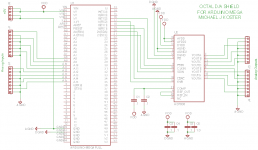
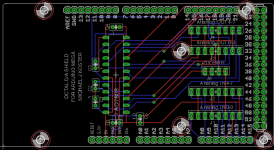
D/A shield
Here is a first cut design for the D/A component that plugs on to the Arduino board (called a shield in Arduino-speak). I provide a +5V power input, 8 D/A outputs, and break out 8 A/D inputs.
The connectors are amp MTA and break the signals out into twisted pair or coax.
Cheers,
Michael
Here is a first cut design for the D/A component that plugs on to the Arduino board (called a shield in Arduino-speak). I provide a +5V power input, 8 D/A outputs, and break out 8 A/D inputs.
The connectors are amp MTA and break the signals out into twisted pair or coax.
Cheers,
Michael
Attachments
I looked at the app note again and made the changes you suggest; thanks.
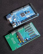
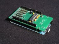
Here is the first PCB stuffed and ready to test, with the Arduino MEGA board it stacks onto.
I'll need to create some library code for the basic setup and operation.
Here is the first PCB stuffed and ready to test, with the Arduino MEGA board it stacks onto.
I'll need to create some library code for the basic setup and operation.
Attachments
- Status
- Not open for further replies.
- Home
- Design & Build
- Equipment & Tools
- A micro-programmable tube tracer/tester