Don't worry about phase shift. Phase shift is a rather ambiguous term and doesn't mean a whole lot in itself.
Wherever there is any delay, there is phase shift. But if the delay is frequency independent, the waveform isn't altered. It's only when the delay is frequency dependent that the waveform is altered.
So group delay (or as Jensen Transformers' Deane Jensen coined it, "deviation from linear phase") is the more important figure to look at rather than just phase.
You can have a phase shift of 20 degrees, but still have a flat group delay. Similarly, you can have a phase shift of 20 degrees and have a big peak in the group delay. It all depends on the characteristics of the low and high pass filter functions.
se
My experience from my tube projects BUT more particularly from the work I did with Hugh Dean on the AKSA 55 Nivarna Plus option to his SS Amp is that when considering the effect on stereo imaging this NOT the case.
All you have to do is some real experiments to turn bald assertion into evidence. Now, if extending the bandwidth of a particular amp has an effect on the sound (verifiable), you then need to take the next step and determine if the positive effect is because of the bandwidth or because the amp has been made more stable. So, get the amp sounding as good as you can, then bandwidth-limit at the input. If you can notice an effect on imaging (assuming you've bandwdth-limited both channels!) in a proper controlled test, you've got an answer. And also a dandy JAES or JASA paper.
The reality is, you and I don't have a source that puts out actual musical information at more than 20kHz (or an octave above for exotica). Even LPs don't have much musical information up there, especially as one wanders from the periphery toward that little hole in the middle. Most energy being pumped out at 5 figure frequencies is just noise.
Moot point, anyway- the specified transformers will hit 80kHz. The tube is ridiculously better.
What do you think of this PCB?
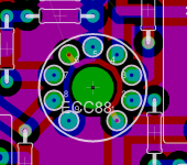
The blue lines are on the soldering-side(bottom), the red lines are on the other side(top), and the picture is viewed from the top side, where the tube, and all other tings will be.
The tube is an E88CC, and the schematic is the schematic, that SY posted in the beginning of this topic, except the input-trafo.
On the PCB there are 2 schannels.
All resistors are 0.6W 1% metal-oxide type.
Here's the PCB:
http://sziget.mine.nu/~danko/aramkor/tube-amp/sy_preamp_pcb.png
SY said:It looks enormously better than my Radio Shack perf-board construction!
Someone who has actually laid out PCBs would be better commenting on this than me.
Is the tube in the right position? I mean, isn't mirrored the tube?
I'm not really sure about it ....
") ) ) I can solder all daaaay
) ) I can solder all daaaay Danko.
It seems that you could feed the pin 4 shortly by routing the track between pin 1 and 9 and below the tube (I see you already have a thru hole for the pin 1.
The same way, pin 9 may be routed to pin 5 below the tube.
My two pences ...
Eagle is a pita to route analog signals

Yves.
It seems that you could feed the pin 4 shortly by routing the track between pin 1 and 9 and below the tube (I see you already have a thru hole for the pin 1.
The same way, pin 9 may be routed to pin 5 below the tube.
My two pences ...
Eagle is a pita to route analog signals
Yves.
Yvesm said:
Danko.
It seems that you could feed the pin 4 shortly by routing the track between pin 1 and 9 and below the tube (I see you already have a thru hole for the pin 1.
The same way, pin 9 may be routed to pin 5 below the tube.
Something, like the attached picture?
Eagle is a pita to route analog signals
Why?
Attachments
Danko said:......What do you think of this PCB?
.....and the schematic is the schematic, that SY posted in the beginning of this topic...
Hi,
I don't see any LEDs and emitter resistors in your CCS. I do see CR networks at the inputs, which do not exist in the original schematic SY posted. Also, your grounding is quite confusing and you're mixing power and signal grounds, which can't be good. You might wish to ask SY if he uses separate RC networks in +B supplies. Also, in SY's design, pin5 is not connected to the ground plus your routing of pin4 is too complex; try rotating the tube by 180 deg.
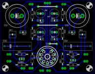
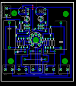
Making PCBs with huge grounding planes is not always the best of approaches. As an exercise, I would suggest designing the board as a single-sided PCB. The picture below shows a similar design of my own (battery-powered tube buffer, ECC86, FET CCS, autotransformer at the output) that migh give you a clearer view of what I am talking about.
Regards,
Milan
Attachments
Milan, I used a common raw supply and separate RC filters. I thought I was clear about that in the text, but apparently not. I'll edit to emphasize this. Thanks!
I will never be able to look at multilayer board drawings and figure out what the heck is going on. I'm glad there are guys like you around.
I will never be able to look at multilayer board drawings and figure out what the heck is going on. I'm glad there are guys like you around.
moamps said:
Hi,
I don't see any LEDs and emitter resistors in your CCS. I do see CR networks at the inputs, which do not exist in the original schematic SY posted.
Yes, I left you the input trafo, becouse I dont need it, and I put an RC-network to the output.
Also, your grounding is quite confusing and you're mixing power and signal grounds, which can't be good. You might wish to ask SY if he uses separate RC networks in +B supplies. Also, in SY's design, pin5 is not connected to the ground plus your routing of pin4 is too complex; try rotating the tube by 180 deg.
Huh, thanks! I will redesign the PCB, to something like yours. I will try to make a central GND-point, and route all gnd into that point.
I will reduce the track width, becouse I see that you use thinner tracks.
Hi,
The drawing is better but maybe I should highlight a couple of things regarding SY's original schematic (not any variation thereof):
1) pin5 can't be connected to the ground,
2) CCS can't be connected to the ground but to -12V PS,
3) +B supplies should be separated.
However, if you wish to do a variation of SY's design (CR network at the input and so on), I think a new thread might be in order.
Regards,
Milan
P.S. It is a common view that routing tracks under the right angle should be avoided.
skyraider said:
One question, regarding the input trans, limited bandwith is good from one point of view. But how about the phase distortion? If the interstage has rolloff at lets say 25kHz, doesnt the phase changes at audible frequency?
Do not confuse phase shift with phase distortion. Two very different animals!
In any case, the f3 of the specified transformer is 80-100kHz. Here's the datasheet:
http://www.jensentransformers.com/datashts/11p1.pdf
Note that the deviation from linear phase at 20kHz is quite small- if there's a concern, it would be at the bass end. And even there, at 20Hz, the deviation is only 1 degree or so.
Alternate tube?
Would I be able to use the Raytheon 5703 in this topology? I ask because they are sitting in my coffee can. Can I make this work or am I just eatin' beans around the campfire?
Character---------- ECC88---- 5703
Heater Voltage----- 6.3 V----- 6.3 V
Heater Current----- 0.365 A--- 0.2 A
Input Cap.--------- 3.3 pF---- 2.6 pF
Output Cap.------- 1.8 pF---- 0.7 pf
Grid to Plate Cap.-- 1.4 pF---- 1.2 pF
Plate Volt. (max)--- 130 V----- 250 V
Plate Dis. (max)---- 1.8 W----- 3.0 W
Plate Volt. (typ.)--- 90 V------ 120 V
Grid Volt.---------- -1.3 V----- 220 ohms
Amplif. Factor------- 33-------- 25
Transconductance-- 12.5 K µmhos 5 K µmhos
Plate Current------- 15 mA---- 9.0 mA
The 5703 is a single triode, so the grid voltage is to be derived from the cathode to bias resistor. (I think) My target is on my forehead. And forgive my ineptitude for cut and paste.
Sure. You'll have a bit lower gain and a bit higher output impedance. Probably a bit higher distortion, but that's already ridiculously low.
To make another tube work, you'll need to change the values of the series resistors in the heater string to reflect the new current and the new required voltage- 12V for your heaters in series. To make another tube work optimally, you'll need to determine what the best operating point (anode voltage and current) is, then adjust the current source and B+ regulator accordingly. First order guess for your tube (which I've never used), I'd plan on 100-120V and 7-8 mA.
To make another tube work, you'll need to change the values of the series resistors in the heater string to reflect the new current and the new required voltage- 12V for your heaters in series. To make another tube work optimally, you'll need to determine what the best operating point (anode voltage and current) is, then adjust the current source and B+ regulator accordingly. First order guess for your tube (which I've never used), I'd plan on 100-120V and 7-8 mA.
- Home
- Amplifiers
- Tubes / Valves
- A Heretical Unity gain line stage