In any case, the f3 of the specified transformer is 80-100kHz. Here's the datasheet:
In that case, its fine.
Keep the updates on the listening results!
I had this version in my living room system for a week or so; it sounded fine. If it did anything other than silently and effortlessly raise and lower the volume, I could not hear it. Getting the system silent unless spoken to was quite worthwhile.
Since than, I've been living with the Mark 2 version (article coming soon), with an output servo, but identical signal and regulator circuitry to what I'm showing here. I've spent this afternoon with a glass of something alcoholic (ok, maybe more than a glass), kd lang, They Might Be Giants, and of course, Tony Rice, as my wife has given me an afternoon off to celebrate Father's Day in the US. The preamp does its job with effortless grace.
Version two, also with a servo, but with RCRC filtration on the plates and some Ampex input transformers, is running my garage/lab system. That's been getting some workout as I try and get the Mark 3 (with novel servo) boxed up and ready for some extended listening.
I should mention that, claiming moderator's privilege, I've been incorporating revisions in the original posts.
boxed up and ready for some extended listening.
If i may be brave and jump the gun with a prediction - it will "silently and effortlessly raise and lower the volume" and be otherwise utterly indistinguishable from any other well designed preamp
")
Mark 3? Just giving the silver wire pushers more business.
analog_sa said:
If i may be brave and jump the gun with a prediction - it will "silently and effortlessly raise and lower the volume" and be otherwise utterly indistinguishable from any other well designed preamp
If all goes well, yes. Novelty can have negative consequences... But the version I'm listening to is quite distinguishable from several others I've tried- it doesn't pass along the buzzes, bamgs, and burbles from the lousy grounds that I can't control.
Don't worry about the rag!
A White follower, done correctly, will work fine. It will require twice as many tubes and elevated heater supplies, while giving essentially no better performance. And it is much tougher to direct couple- which will be the next chapter in this saga.
My previous preamp also used JFETs as cathode loads. It worked well enough for me to use it for 20 years or so.
Hi Sy and all!
For this schemetics to connect the power supply to the heater and power supply catode tube follower on her well done differently or should that be done?
Thank you for your cooperation and assistance!
P.S.
My previous preamp also used JFETs as cathode loads. It worked well enough for me to use it for 20 years or so.
SY, where is the schematics??
thank you!
Attachments
Last edited:
Member
Joined 2009
Paid Member
... which will be the next chapter in this saga...
any updates?
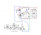
Apologies for raising this ancient thread from its long sleep. I am interested in building this preamp because I too have messed up grounds, that I also can't control, and that result in super quiet amps when shorting plugs are inserted, but always some sort of hum or buzz with any source. I have the required input transformers and all the tube stuff needed (and then some), but not the solid state stuff in the schematic. Would anyone like to help an old fashioned tube head by suggesting available replacement parts for the no longer available solid state elements included in this preamp? I read SY's article on his website, and he said that some of the choices he made were non critical, but I don't know much at all about transistors, and am feeling anxious about what to replace the discontinued parts with. I promise to build this preamp and post my progress here if I can get appropriate replacement parts for the solid state stuff. The parts I can't get are MJE340, MPSU10, and LM412. I suppose I could skip the power supply portion and go with more RCs or LCs. I have lots of both on hand, but I may as well do it all. Also, there is an inductor that is not labelled in the schematic (circled in red)...

Last edited:
Regardless of what you want to have/build: it is effective to solve that grounding issues for any audio setup. Hint: it involves simple electrical work that is low level and does not take too much of your time. Quite rewarding as well.
If you make pictures in detail and explain the issues I am sure many here can help you solving the riddle.
If you make pictures in detail and explain the issues I am sure many here can help you solving the riddle.
Do mean solving the actual electrical issue that is causing the humm/buzz? That would probably be best, but I do need a buffer stage that is very transparent, has no more than unity gain, and that has a volume control to feed a couple of power amps that I own. This preamp seems to fit the bill while also providing the isolation that I need. I am also all for fixing the hum and buzz problem at the source as well.Regardless of what you want to have/build: it is effective to solve that grounding issues for any audio setup. Hint: it involves simple electrical work that is low level and does not take too much of your time. Quite rewarding as well.
If you make pictures in detail and explain the issues I am sure many here can help you solving the riddle.
OK then reread second alinea of my post.
Solving issues at the root and definitive once used to be the only definition of solving an issue Not probably best but absolute best in practice.
No setup with whatever topology will perform as it should when the basic requirements are not met.
Solving issues at the root and definitive once used to be the only definition of solving an issue
Not probably best but absolute best in practice.No setup with whatever topology will perform as it should when the basic requirements are not met.
The part you asked about is a 12 volt relay.
However as the schematic would receive a failing grade from my friend who teaches drafting, I suspect that although the design would work, there may be significant issues following it properly.
As to the relay you would need, not shown on the drawing is that it should have gold over silver crossbar contacts intended for audio use.
JP is right it would be much easier to find your problem and fix it.
However if you do not or cannot fix it, then the only part you require is the audio isolation transformer. The circuit as shown is probably not doing what you seem to expect.
If you want a bit of gain or impedance matching just use a different transformer.
Last edited:
Okay. I should probably start another thread on this issue specifically. Where would be the best placeOK then reread second alinea of my post.
Solving issues at the root and definitive once used to be the only definition of solving an issue
No setup with whatever topology will perform as it should when the basic requirements are not met.
To put it?
It was originally my intention to just build a cathode follower to fit my requirements for unity gain, a volume control and low output impedance, but the addition of the input transformer in this design seemed to also take care of another issue that I have in my system with some amps.The part you asked about is a 12 volt relay.
However as the schematic would receive a failing grade from my friend who teaches drafting, I suspect that although the design would work, there may be significant issues following it properly.
As to the relay you would need, not shown on the drawing is that it should have gold over silver crossbar contacts intended for audio use.
JP is right it would be much easier to find your problem and fix it.
However if you do not or cannot fix it, then the only part you require is the audio isolation transformer. The circuit as shown is probably not doing what you seem to expect.
If you want a bit of gain or impedance matching just use a different transformer.
- Home
- Amplifiers
- Tubes / Valves
- A Heretical Unity gain line stage