Thank you very much.
The tape seems to be silver and i didnt knew..
the tape is ordinairy double sides foam tape, white in colour.
Why do you need equalisation? Do you have nasty spikes (resonances) in the hight frecvency range?
Did you stuffed the cillinders with dumping cloath?
This aluminium wire is interesting but i think you still need to put some glue on the edges of the coil to stick well. I think of that because of the vibrations and dont know how hard will get that wire adhesive..
I stuffed it, does something but its not all. btw i made a single sides one as well, wich is still push pull, somehow i find the design with to membrames behind each other not the best idea to be honest. i tried one with only lobbes on the front side. all the weird peaks up till 1khz to 5 Khz wil go away, i think i even had slightly lower distortion. but not by much. only concern will be if its linear this way, since it uses the strings to center the coil. and helps the back and forth motion. i tried 2 differend types of paper. and result is the same everytime. there is a huge drop at 14 khz move the mic few centimeters and there is a huge peak at 15khz. diferent papers same result. when you decrease the void in betweet the cylinders by making them bigger it flattens a bit, but still does not reach 20khz without a huge drop. i can hardly believe the statement of 300 to 20khz for the janus. at least not without EQ. i do must say when you listen to it it does not sound like something is missing. on the other hand we might be to old
") and it will smear better in the far field
and it will smear better in the far field The bonding of the wire is to get it out of the bobine, after that i can always apply few drops of cyanacrylate or something.
i think the problem with the hgh frequency lies in the fact that where the cylinders meet, there will be in fase material and material that is delayed a tiny bit(because of the strong curve there) but enough to cancel, if you move a bit on the axis it will add up instead of being out of phase, hence the high peak. since the most output is obtained in the middle section where the 2 pieces meet, the peaks and valley are big as well. another thing is that inn this area the membrame changes shape the most so the drift is over a wide frequency. me might get better result by flaten the front and let the cylinder move back after a few centimeters. where it does not have as much high frequency output this is still a guessing game, i am no pro. im just gone try and try to understand why its acting so weird.
Last edited:
Hi Wrine, last night i was thinking about what you said about the hight frecvencies rolloff.. I found this patent :
Patent US1740161 - Device for the reproduction of sound - Google Patents
Its related to the rubanoide, BUT, because it has only contact point the total surface area from front to back is bigger.
The only problem is that i dont understand the coil system and how are the coils been arranged. And where are the strings for centering the membrane in the gap?
This patent has been improved and selled by Lineaum company with aprox the same frecv band as the rubanoide...
I think this is what you want to try.
well, i tried many configurations today, and im not sure anymore what it could be, when i make the cylinders smaller the HF extends.. wich results in les low end(so maybe not even extending but bringing the low end down).. i have a underhung motor maybe ill try a overhung. really not sure what is goign on atm.
well, i tried many configurations today, and im not sure anymore what it could be, when i make the cylinders smaller the HF extends.. wich results in les low end(so maybe not even extending but bringing the low end down).. i have a underhung motor maybe ill try a overhung. really not sure what is goign on atm.
Hi Wrine,
So, practically we have two sollutions to make a wide bander from this design:
1) Make another smaller rubanoide like yours with smaller cylinders thin paper, small gap, low mass coil and strong magnets. (i dont like this sollution).
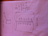
2) This is another ideea of what i think of (the photo attached).
Attach strips of thin paper or film as close as possible to the coil without interferring with the windings..
The philosophy behind this idea is that if you make a rubanoide, even with 90g/sqm Tedlar Foil (used on the back of photovoltaic solar panels), wich i think is indicated here, because of the weight of the cylinders they cannot make sound as we wish because of the bondings with the coil and the laterall bars, and because of the thick paper.
If we use strips of film tape (like in the photo attached) or paper they are lighter, they can vibrate with ease because they are bonded just on one syde and other advantages are that if we use a very light material and few quantity of glue we can keep overall mass low. We have to be carefull at how long these strips are because they cand resonate as well.
I think in your case Wrine 1 inch is sufficient..
And keep the cyllinders interiors damped with material, and the membrane also damped with tape foam.
What do you say about this ideea?
Attachments
Last edited:
yeah thought of that as well , but the papers are suspended in the air?(on the outer side just liek a whizzer) or stick to the cylinder, that would defeat the purpose. or do you make cutouts in the cylinder and ad lighter paper on that spot>?
EDIT, sorry you anwser is in the drawing only to the base. yeah we will have some really anoying resonance, mainly, the base res of the length of paper. wich is gone be huge.
the problem is i still cant wrap my head around why its acting so weird, and it des not seem to have anything to do with weight, since i had 2 different kind of papers one really heavy on light and result is almost the same. i think it has to do with either shape , or the bonding of coil to paper and the tranfer function of it. almost like its limited to give the fast pulses trough to the paper its sticked on.
EDIT, sorry you anwser is in the drawing
only to the base. yeah we will have some really anoying resonance, mainly, the base res of the length of paper. wich is gone be huge.the problem is i still cant wrap my head around why its acting so weird, and it des not seem to have anything to do with weight, since i had 2 different kind of papers one really heavy on light and result is almost the same. i think it has to do with either shape , or the bonding of coil to paper and the tranfer function of it. almost like its limited to give the fast pulses trough to the paper its sticked on.
Last edited:
I read that the best results where obtained using a foil pcb. I dont know if i made muself understood, but its a pcb etched without the hard support instead its layed on a thin film.. I dont know how its made but it has better results than a classic copper coil.. I also think that the glue its very important. My ideea was to stick the coil with a hard laquer and then try somehow to put some rubber like adhesive on the edges (in my country its called "Polyadez"). This way the coil will transmit the vibrations more accurate and the rubber like adhesive will dampen abit the nasty spikes. What do you say about this idea?
Another interesting ideea is adding another elastic string in plus from the top to exactly the middle of the cyllinders on just one face. I think this will limit allot the resonances.. But it will be hard to tension both elastics from the top..
You will have on the top two elastics and just one on the bottom.
You will have on the top two elastics and just one on the bottom.
i got 2 elastics on top and 2 bot (front and rear.) i noticed that spring tension is not affecting the high frequencies. i indeed think its maybe the coil, the material its glued on and the glue itself. for high frequencies i would not use any rubber kind of glue since it damps . high frequencys are pretty easy to damp
i now have a piece of carton with a coil glued on it with super glue, i weight it at 4 grams on a cooking scale so not verry precise. and measure what it does (withouth the whole cylinder) i can measure that even only this piece cant reach the 20Khz. so if the coil itself and the piece its glued on cant reach it, its not gone reach it when adding the rest of the membrame. i now try to stiffen the carton with liquid glass. to see if it does something and how much weight it adds. (so i could take thinnner paper)
about the flexible PCB i just ordered an solid ink printer to do just that , at least if i can find me some cheap FPC (flexible printer circuit) base material to try it on, i might first try a home made laminate with ordinairy copper tape or alumnium on mylar or any other substrate. also i bought it on a auction site and i must say i did not really trusted the seller. but i did pay the guy in front just a gamble
i now have a piece of carton with a coil glued on it with super glue, i weight it at 4 grams on a cooking scale so not verry precise. and measure what it does (withouth the whole cylinder) i can measure that even only this piece cant reach the 20Khz. so if the coil itself and the piece its glued on cant reach it, its not gone reach it when adding the rest of the membrame
. i now try to stiffen the carton with liquid glass. to see if it does something and how much weight it adds. (so i could take thinnner paper)about the flexible PCB
i just ordered an solid ink printer to do just that , at least if i can find me some cheap FPC (flexible printer circuit) base material to try it on, i might first try a home made laminate with ordinairy copper tape or alumnium on mylar or any other substrate. also i bought it on a auction site and i must say i did not really trusted the seller. but i did pay the guy in front just a gamble
Last edited:
250g/sqm is allot my friend. Audionec is using for their rubanoide a special hand made paper at around 200g/sqm (dont know exactly) and Francois Deminiere Tedlar for the Janus 50 at 90g/sqm.
My opinion is that the Janus 50 is going as high as 18khz-20khz ALLONE because the Tedlar he uses its conposed from a thin film of pvf and a special paper. The thin foil gives the frecv up to 20khz and the paper stops the resonances... Thats what i think.
The biggest problem that i have is where can we source the Tedlar (in Europe) used for the back of the photovoltaic panels???
Cheers
Segiu
i really dont think the tedlar is like magic. i might indeed be the coil. i just ordered some copper clad 0.125 mm thick this should be able to pass my solid ink printer when it arives (if it ever does) if the paper was the problem i should at least get to high frequencys when using a 80grams paper with a coil.
could also be magnets strenth. or something else so many variables tedlar is pretty expensive, and can be bought for like 60 euro for a small piece.
could also be magnets strenth. or something else so many variables
tedlar is pretty expensive, and can be bought for like 60 euro for a small piece.i really dont think the tedlar is like magic. i might indeed be the coil. i just ordered some copper clad 0.125 mm thick this should be able to pass my solid ink printer when it arives (if it ever does) if the paper was the problem i should at least get to high frequencys when using a 80grams paper with a coil.
could also be magnets strenth. or something else so many variables
You are right. There are so much variables.. I also think that if you increase the magnets strenght your SPL goes higher and the hights popes out but not much.
Have you tried square wire for the coil? Not round wire. With the square coper wire you can use less wire for the same impedance and at the same time have aprox twice the surface contact with the membrane and go all the way in an underhung design because the coil has less surface..
Sergiu
The diam of one cilinder on the janus 50 in 10 cm...
After reading some other patents of the Lineau i found an interesting ideea there:
Cut a hole inside the bobin (in the space inside where its full of paper), with the same shape as the bobin. I think this reduces the mass in this critical area of the vibrating system, and breaks the pathway for immediate end-to-end standing waves, and forms a "hinge point" in the otherwise ridged central beam area and i think this will detension abit the paper from the interior of the coil and lower the resonances as it did in other Lineaum products..
Cheers
Sergiu
- the dia is around 9.3 cm, i calculated it back from the outline of the circle wich was 29.5cm. this includes the flat piece of around 4 or 5 cm that is in between the magnets. total weight is 33 grams including the coil.
I dont have any square wire thank god hehe , i bought to many random crap for this project already, as always... until i decide its not usefull or not worth my effort(money) since it gets to expensive. i did not reach that yet in this project, since everything is pretty cheap. i just want to solve the high frequency so i can move on to the good stuff like spl and distorting and esthetics. since i dont even hear the 15khz and above, i just want it to be there
- you mean a hole in the middle of the coil ? where there is only paper >? thought of that idea as well but was afraid it will disturp the rigidnes of the piece the coil is glued on.
another good reason to DO it is because when the coil is sandwiched both the papers dont really adhire good in the middle so there is a cavity of glue, although i also did a versoin with the coil glued on only one paper, that did not resulted in anything spectactulair, so again no big results
i might poke a hole in the excisting version i have laying around ill try measure it before i do that, and after. but that has to wait till tomorow
- the coil is an underhung already, since my metal is 10mm thick, and the coil width around 5 or 6 mm.
I dont have any square wire
thank god hehe , i bought to many random crap for this project already, as always... until i decide its not usefull or not worth my effort(money) since it gets to expensive. i did not reach that yet in this project, since everything is pretty cheap. i just want to solve the high frequency so i can move on to the good stuff like spl and distorting and esthetics. since i dont even hear the 15khz and above, i just want it to be there - you mean a hole in the middle of the coil ? where there is only paper >? thought of that idea as well but was afraid it will disturp the rigidnes of the piece the coil is glued on.
another good reason to DO it is because when the coil is sandwiched both the papers dont really adhire good in the middle so there is a cavity of glue, although i also did a versoin with the coil glued on only one paper, that did not resulted in anything spectactulair, so again no big results
i might poke a hole in the excisting version i have laying around
ill try measure it before i do that, and after. but that has to wait till tomorow - the coil is an underhung already, since my metal is 10mm thick, and the coil width around 5 or 6 mm.
Last edited:
Here is what i have in mind my friend:
1.

2.

3.

4. http://patentimages.storage.googleapis.com/pages/US5230021-6.png
5. This is very interesting :

It looks like they added some limiters to the memnrane to linearise the movement of it..
This is one of the latest patents wich i found very interesting because the limit the resonances with allot of cuts in the membrane:
Patent US5230021 - Audio transducer improvements - Google Patents
1.
2.
3.
4. http://patentimages.storage.googleapis.com/pages/US5230021-6.png
5. This is very interesting :
It looks like they added some limiters to the memnrane to linearise the movement of it..
This is one of the latest patents wich i found very interesting because the limit the resonances with allot of cuts in the membrane:
Patent US5230021 - Audio transducer improvements - Google Patents
"FIG. 6 shows web 60 in a straightened, partially preassembled condition with triangular tangs 66 cut and folded in position for attachment to the magnet pole pieces 52. In this embodiment, one edge of each tang is an extension of either the upper or lower portion of the web, depending on whether the tang is the upper or lower tang. The coil 70 (shown in dashed lines) is an elongate looped coil of wire forming a vertically oriented generally oblong or rectangular shape, with a pair of opposed straight, vertically oriented wire segment portions being spaced apart to align with the magnet pole pieces 52. Similar tangs are cut in web 62 (not shown) and folded in the opposite direction as those shown, providing a symmetrical diaphragm.
As further shown in FIG. 6, the diaphragm 46 is provided with a vertical row of hinge perforations 72 on each side of the coil 70. The perforations are preferably aligned with the folded tangs 66 and are positioned within about 1/4 inch of the coil 70 and hence within about 1/4 inch of the joined expanse portion. The tangs are integral extensions of the web formed by folding pre-slitted tab-like portions of the web. Positioning the perforations 72 close to the coil 70 effectively reduces the mass of the rigid center portion 64 of the diaphragm 46. The perforations 72 may be circular as shown or, alternatively, may be any other shape including oblong, square or elliptical and may alternatively be sheared line segments with no diaphragm material removed. FIG. 6 further shows the center portion 64 defining mass reduction holes 74, the advantages of which are discussed below with reference to FIG. 7.
Each row of perforations acts like a hinge to permit a less constrained, more responsive movement of the central diaphragm expanse portion 64. The size of the perforations is not critical, only the proportion of material removed affects the key property of hinge-like flexibility at the edges of the center portion 64. Along the hinge center line of each row of hinge perforations 72, the sum of the linear dimensions of the perforations is preferably between about 10% and 50% of the full linear dimension of the web 60 along the same vertical line. With current materials used, the perforations define a pair of hinge lines at which the web material is preferably about 80% connected and 20% perforated. Thus, it is apparent that the web shown in FIG. 6 is less than 20% perforated and thus less than optimum. The foregoing parameters likely will become better defined with further experimentation.
The added hinge-like flexibility provided by the perforations 72, permits the efficiency of the transducer at very high frequencies to be substantially increased as the rigid central portion 64 of the diaphragm 46 is able to move more independently of the mass of the web curved portions 60a, 60b, 62a, 62b. In addition, the reduced mass resulting from the removal of the diaphragm material is the close vicinity of the central portion may also contribute to this effect. Experimental analysis has shown a 3 to 6 db increase in output over the 12 to 24 kHz high frequency range, with no sacrifice in efficiency at the low end of the transducer's output. Previous attempts to provide an improved high frequency efficiency, such as using a lighter and more flexible diaphragm material, have resulted in an undesirable drop off in low frequency performance.
FIG. 7 shows a web 60 having an alternative arrangement of tangs 66a and perforations 72a. In this embodiment, the tangs are rectangular and folded perpendicularly outward from their original pre-folded positions in the center portion 64 of the diaphragm 46 covering the end portions of the coil 70. While it is generally desirable that the coil be supported by and rigidly affixed to the webs 60 and 62, this is only important along the vertical portions of the coil (shown in dashed lines), which magnetically interact with the magnets shown in FIGS. 3 and 4. The exposed end portions of the coil 70 need not be supported. A further advantage of the FIG. 7 web construction is that the exposed end portions of coil 70 dissipate accumulated heat more effectively, as they are directly exposed to the environment.
The perforations 72 are shown in FIG. 7 as oblongs aligned axially in a vertical row, but any shape may be used as discussed above with reference to FIG. 6. As in FIG. 6, FIG. 7 shows only a single web 60. A similar web 62 would be adhered at the central portion 64 to create a sandwich, with the coil 70 between the webs. FIG. 7 also shows central mass reduction perforations 74 defined in the central portion 64 of the diaphragm, and centered entirely within the coil 70 to reduce the mass of the central portion 64. The central portion 64 is rigid and functions essentially as a planar beam translating in its own plane. The mass reduction provided decreases the inertia of the central portion 64 and results in a slight improvement in high frequency efficiency, with a subjectively perceptible increase in the quality of sound perceived as quickness."
Last edited:
"FIGS. 8 and 9 show the high frequency transducer 20 with an alternative diaphragm centering mechanism. Instead of the tangs 66 formed of the diaphragm 46 to align the diaphragm within the magnet gap 40, as shown in FIGS. 3-7, the embodiment of FIG. 8 uses a pair of elongated foam members 76 to retain the central portion 64 of the diaphragm centrally within the magnet gap 40. Each foam member has a width 78 sized to closely fit between the front and rear chassis plates 30, 32. Each foam member 76 has a slitted central neck portion 80 with a reduced width. A slit 82 is cut across the width of the neck portion to a depth of about one-half the thickness of the foam member. The foam members 76 are attached to the high frequency transducer 20 by mating the slits 82 with the corresponding top and bottom edges of the central portion 64 of the diaphragm 46 and adhesively securing the sides 84 of the foam member 76 to the inner surfaces of the chassis plates so that the foam members rest against the magnets 36, 38 and are entirely positioned between the chassis plates 30, 32. In addition, the slits 82 are adhesively secured to corresponding edges of center portion 64 of the diaphragm 46.
The diaphragm 46 is thereby retained perfectly centered within the magnet gap 40 by the slits 82 provided in the elongated foam members 76. Because the foam members 76 are formed of a lightweight open cell foam having a low resistance to small displacements, they have a negligible damping effect on high frequency vibrations of the diaphragm 46, yet they preserve a central alignment of the diaphragm 46 that is not susceptible to shifting over time."
"FIGS. 10 and 11 show a wide range, mid- to high-frequency transducer 90 embodying the invention as an essentially improved version of the audio transducer disclosed in U.S. Pat. No. 4,903,308. Transducer 90 operates on the same general principal as the high frequency transducer 20, with a diaphragm 46 formed by webs 60, 62, as a figure-eight shape. The central portion 64 of the diaphragm 46 passes through the magnet gap 40 (FIG. 11) with a coil 70 (not shown) sandwiched between the webs 60, 62 and residing within the magnet gap in the manner precisely described. In this larger embodiment of the transducer 90, a larger chassis 92 retains the diaphragm 46 and the magnet assemblies 36, 38. The chassis 92 is formed generally of spaced apart vertical diaphragm retaining members 94, 96 and two opposed pairs of central opposed vertical magnet retaining members 98, 100 located between the diaphragm retaining members 94, 96. The magnet retaining members 98 comprise a pair of rigid vertical planar members spaced apart sufficiently so that magnet assembly 36 may be rigidly affixed therebetween to define the magnet gap 40 with the opposite magnet assembly 38, which is similarly affixed between the opposing pair of magnet retaining members 100.
FIGS. 10 and 11 further show a diaphragm centering means including triangular alignment tangs 66b formed by V-shaped cuts in each web 60, 62. The apex of each "V" forms a free end that points horizontally away from the central portion 64 of the diaphragm 46. The base of each "V," that is, the portion closest to the central portion 64 of the diaphragm 46 and integrally attached to the diaphragm at a fold line 102, extends substantially perpendicularly from the web in a plane parallel to the exposed exterior surface of the adjacent magnet retaining pair member 98, 100 so that the tang 66b may be adhered to or secured against the adjacent retaining member. With the diaphragm 46 suitably centered in the magnet gap 40, the free end tips of the tangs are adhered or clamped to the exposed surfaces of the magnet retaining pair members 98, 100 and covered by rigid elongated tang retaining members 104, which are adhesively affixed to the magnet retaining pair members 98, 100 so that the tips of the tang 66 are sandwiched therebetween. The cuts forming the tangs 66 have the additional advantage of providing a flexible hinge line as discussed above with respect to the hinge perforations 72 and 72a of FIGS. 6 and 7. Additional perforations (not shown) between tangs 66b may be provided to increase the diaphragm's flexibility still further.
FIGS. 10 and 11 also show a pair of cylindrical acoustic dampers 110 oriented vertically and positioned between the respective diaphragm retaining member 94, 96 and magnet retaining pair 98, 100 in each chamber defined by the respective circular web 60, 62. Each damper 110 is formed by a cylindrical tube of perforated webbing, such as a flexible plastic mesh 112, which is filled with a core of lightweight fibrous stuffing 114. The stuffing 114 may be any suitable material, such as wool, felt, cellulose fiber or fiberglass. The dampers prevent internal acoustic reflections and vibrations from degrading the output sound."
"FIG. 12 shows preassembled web 60 of the embodiment of FIGS. 10 and 11 with the tangs 66b shown as "V" cuts and folded along fold lines 102. Tangs 66 are arranged in two vertically aligned rows, one row on each side and located about 1/4 inch from coil 70. Like tangs 66, tangs 66b are formed as integral folded extensions of the diaphragm.
FIGS. 13 and 14 show an alternative configuration of the diaphragm 46 for use on the mid- to high-frequency range transducer 90 of FIGS. 10 and 11. Web 60 is provided with a plurality of circular holes 116 arranged in vertical rows registered with the linear vertical portions of the coil 70. The holes 116 are spaced apart in each row by a center-to-center distance greater than twice the diameter of the holes. The holes are staggered in each row so that the holes in one row are aligned with the mid points between centers of adjacent holes in the opposite row. The web 62 is provided with an identical set of holes 118, shown in dashed lines. Webs 60, 62 are registered with the holes 116, 118 aligned in reverse registration so that each hole 116 overlies a solid unbroken portion of adjacent web 62 and each hole 118 underlies a solid, unbroken portion of adjacent web 60. Therefore, there are no openings passing entirely through both webs 60, 62. The coil 70 is adhesively laminated between the webs 60, 62 so that its vertical linear sections are generally aligned with the rows of holes 116, 118. Because of the arrangement of holes 116, 118, every point along the entire length of the coil 70 is adhered either to web 60 or web 62 or both. This prevents any undesirable relative motion between the coil 70 and the webs 60, 62. Because the webs 60, 62 are adhered only to the coil, and not to each other in the region beyond the periphery of the coil, the holes 116, 118 provide the hinge-like flexibility discussed above, and produce high frequency efficiency improvements without sacrificing low frequency efficiency. In addition, heat in the coil 70 is readily dissipated by the substantial portions exposed to air through the holes 116, 118, while performance is maintained with a rigidly attached coil.
FIG. 15 shows an alternative diaphragm arrangement for the transducer 90 of FIGS. 10 and 11. An articulated row of perforations 72b is defined entirely through the diaphragm 46, penetrating both webs 60, 62 on both sides of the coil 70. The perforations as shown are circular, but numerous other shapes are contemplated and may be substituted. The holes 72b of this embodiment are separated by at least a minimal distance from the coil 70 to ensure that the coil is entirely adhered to the diaphragm 46. At least a portion of some of the perforations preferably are within at least about 1/4 inch of the coil 70 to provide optimal flexibility in the diaphragm 46 for high frequency efficiency. FIG. 15 further shows a centrally aligned row of mass reduction perforations 74b positioned in a vertical row within the coil 70. The perforations 74b may pass entirely through the diaphragm 46 or may each be defined only in a single web 60 or 62 so that through holes are not provided through the diaphragm. In an alternative embodiment, a thin film or sheet of thin material may be provided between the webs 60, 62 to close the perforations 74b while allowing the advantages of substantial weight reduction.
FIG. 16 shows an additional alternative embodiment, with diaphragm 46 having hinge perforations 72c defined in the diaphragm 46 as small diameter circular holes in a linear configuration. In this embodiment shown, about 20% of each row is perforated while about 80% of the diaphragm remains connected at each row. FIG. 16 further shows the optional mass reduction perforations 74c.
FIG. 17 shows a further alternative diaphragm 46 embodiment having elongated rectangular perforations 72d that provide a hinge-line of approximately 50% perforated length and 50% connected length.
It will be appreciated that the perforations 72 located along the outside vertical edges of coil 70 can have a wide variety of shapes and sizes. The perforations 72, for example, have a diameter of about 1/4 inch and are spaced apart about 1/4 inch. Perforations 72a have a length of about 1/8 inch and are spaced apart about 1/4 inch. Similarly, perforations 72b have a diameter of about 1/8 inch and a spacing of about 1/4, and perforations 72c have a diameter of about 1/2 inch and a spacing of about 1/4 inch.
The increased flexibility and compliance which the perforations 72 provide the diaphragm is, in part, a function of the distance of the perforations from the vertical edge of the coil (which edge also defines the edge of the rigid central portion formed by adhering the two webs together). The perforations preferably eliminate diaphragm material along a hinge line within about 1/4 inch and, most preferably, within 1/4 inch or less of the vertical edges of the central joined-together portion of the webs. As this distance increases, spacing the perforations further from the coil, the increased flexibility and compliance drops off because the perforations are located farther from "hinge zone" on either side of the rigid beam-like central portion and hence farther from the primary high frequency radiator zone.
As the perforations move toward the coil to the point where they overlap the coil and extend into the rigid central portion area, the perforations cease to contribute increased flexibility but still improve the diaphragm performance to some extent by reducing the mass of the central portion which oscillates in response to th changing magnetic field.
For balance, it is important that the perforation pattern on both sides of a vertical line bisecting the coil be substantially symmetric. When web 60 in FIG. 13 is considered by itself, the perforations 116 do not provide a perfectly symmetric pattern as just noted. However, the webs 60 and 62 together do provide a balanced symmetry as FIG. 13 illustrates. It is also desireable that the perforation patterns above and below a horizontal line bisecting the coil also be symmetric"

"FIG. 18 shows an alternative approach for suspending and aligning the diaphragm 46 in the magnet gap 40. The diaphragm defines a pair of vertical slits 122 at both the upper and lower edges thereof, with the slits being aligned to register with the magnet pole plate surfaces 52 when the diaphragm is installed. An elongated rectangular tab 124 is inserted into each slit 122 so that it extends perpendicularly by an equal amount from each side of the diaphragm. Each tab is preferably formed of a strong and flexible sheet of material similar to the diaphragm. The free ends of each tab 124 are adhered to the magnet pole plates. The tabs have sufficient thickness that the diaphragm slits 122 do not shift or slide along the tabs during normal use. A deliberate force may be used to adjust the alignment during assembly.
FIG. 19 shows an alternative alignment approach using similar tabs 124 as in the embodiment of FIG. 18. Instead of retaining the tabs 124 in slits 122, however, the diaphragm defines tab holes 126 corresponding with the slit 122 positions of FIG. 18. The tab holes 126 are sized slightly smaller than the width of the tabs 124 so that the tabs resist sliding through the holes 126. The tabs 124 may thus need to be curved to pass through the holes when inserted during assembly. The tab holes 126 are shown as circular, but any shape, such as an ellipse or diamond, that snugly retains the tab 124 in a vertical plane is suitable."
Last edited:
I cut from the patent that I posted above only the fragments that we need.
The rubanoide that we try to figure it out has been done and working and has been a product for sale in the 90's to 2000 year at a smaller skale with succes and had allot of admirers for the spaciousness and transparency and neutrality qualities. Others did this design so why cant we?
I study allot of this speaker, search allot of things and imporvements for it because i like the dispersion of it and the qualities posted earlier.. Also i like that it has no sweet spot like allot of speaker have, so enyone cand enjoy the sound..
I want to make myself a pair. In July i will make an order for the magnets and steel for the Janus 50.
Till then i will support you Wrine with all the info that i can find. So dont buy allot of stuff that you dont need... You will end up like myself, with allot of stuff that you dont need. Be patience. Lets try to figure out the case, find a sollution and then buy.
Till my order for the neo magnets i also have a work in progress on my freshly finished Hiraga Super Class A Amplifier (35W/8 ohm). Im working on the enclosure allot . I think its the hardest part of an amplifier. I jope to finish it at the end of June. Look some picture bellow of the work in progress:
Up syde
Down syde
Metal case
The radiators arranged to obtain a "chimney effect"
Insyde are the transistors..
Excuse the OFFTOPIC.
Cheers
Sergiu
PS : THE PATENT POSTED ABOVE IS ONLY FOR DIDACTIC USAGE, NOT FOR COMMERCIAL.
The rubanoide that we try to figure it out has been done and working and has been a product for sale in the 90's to 2000 year at a smaller skale with succes and had allot of admirers for the spaciousness and transparency and neutrality qualities. Others did this design so why cant we?
I study allot of this speaker, search allot of things and imporvements for it because i like the dispersion of it and the qualities posted earlier.. Also i like that it has no sweet spot like allot of speaker have, so enyone cand enjoy the sound..
I want to make myself a pair. In July i will make an order for the magnets and steel for the Janus 50.
Till then i will support you Wrine with all the info that i can find. So dont buy allot of stuff that you dont need... You will end up like myself, with allot of stuff that you dont need. Be patience. Lets try to figure out the case, find a sollution and then buy.
Till my order for the neo magnets i also have a work in progress on my freshly finished Hiraga Super Class A Amplifier (35W/8 ohm). Im working on the enclosure allot . I think its the hardest part of an amplifier. I jope to finish it at the end of June. Look some picture bellow of the work in progress:
Up syde
An externally hosted image should be here but it was not working when we last tested it.
Down syde
An externally hosted image should be here but it was not working when we last tested it.
Metal case
An externally hosted image should be here but it was not working when we last tested it.
The radiators arranged to obtain a "chimney effect"
An externally hosted image should be here but it was not working when we last tested it.
Insyde are the transistors..
An externally hosted image should be here but it was not working when we last tested it.
Excuse the OFFTOPIC.
Cheers
Sergiu
PS : THE PATENT POSTED ABOVE IS ONLY FOR DIDACTIC USAGE, NOT FOR COMMERCIAL.
- Home
- Loudspeakers
- Planars & Exotics
- A DIY Ribbon Speaker of a different Kind