The way a shortening ring (Faraday ring) works in a normal driver is as follows. The voice coil can be seen as the primary turn of a transformer, with the pole piece as the core. If AC is put on the voice coil, it modulates the magnetic field in the pole piece, very much like what happens in a transformer with the secundary opened. This flux modulation generates a current in the voice coil which counteracts the AC put on the VC. This causes the impedance to rise and this is what you measure on the high end where the curve slopes opwards. Flux modulation is the underlaying mechanism that causes a voice coil to display inductance.
By employing a shortening ring, you introduce a secondary winding on the pole piece, and the same thing happens as when you close the secondary on a transformer: the flux modulation gets 'sucked up' by the shortened secondary, and this shows in measurements as a lowering of inductance. More current will flow, all other things being equal.
To do a similar thing with this driver, we have to analyze the magnetic assembly in order to see how flux modulation occurs and where we can introduce a shortening ring to fight flux modulation. There appear to be two locations for this. The first one is inside the magnetic gap. A piece of copper foil with the same shape as the voice coil could be attached to the iron of the magnetic assembly where it faces the magnetic gap, on each side. It is important that it is not just strips on the iron, but that they are shortened on the top and bottom.
Another location would be on the other end of the magnet assembly, the side facing away from the magnetic gap. It will be far less effective, but part of the flux modulation might travel through the iron and can be stopped by putting a similar copper strip assembly on that side.
Last edited:
The way a shortening ring (Faraday ring) works in a normal driver is as follows. The voice coil can be seen as the primary turn of a transformer, with the pole piece as the core. If AC is put on the voice coil, it modulates the magnetic field in the pole piece, very much like what happens in a transformer with the secundary opened. This flux modulation generates a current in the voice coil which counteracts the AC put on the VC. This causes the impedance to rise and this is what you measure on the high end where the curve slopes opwards. Flux modulation is the underlaying mechanism that causes a voice coil to display inductance.
By employing a shortening ring, you introduce a secondary winding on the pole piece, and the same thing happens as when you close the secondary on a transformer: the flux modulation gets 'sucked up' by the shortened secondary, and this shows in measurements as a lowering of inductance. More current will flow, all other things being equal
To do a similar thing with this driver, we have to analyze the magnetic assembly in order to see how flux modulation occurs and where we can introduce a shortening ring to fight flux modulation. There appear to be two locations for this. The first one is inside the magnetic gap. A piece of copper foil with the same shape as the voice coil could be attached to the iron of the magnetic assembly where it faces the magnetic gap, on each side. It is important that it is not just strips on the iron, but that they are shortened on the top and bottom.
Another location would be on the other end of the magnet assembly, the side facing away from the magnetic gap. It will be far less effective, but part of the flux modulation might travel through the iron and can be stopped by putting a similar copper strip assembly on that side.
thanks for the explanation , so i might just couple the top side and the bot side and see what happens? although that is a brute solution as you discribe there is more to it in real life
")
Last edited:
Here is a measurement without and with copper tape on the inside of the gap, i did not connect both sides to eachother, might be doing that in a final version with a bit more solid tape or foil. this stuf is only 40 micron or something.
pink is with no tape
green is with. most weird is overal the resisance is higer and where it peaks its a bit lower. be it only 0.6 ohm or something
is this the result i should expect? the copper layer consist of 8 pieces of thin copper tape side by side, i can imagine it works better with like 0.1 mm copper out of one piece, making a loop?
No , I expected that the impedence above 2kHz got lower.
Try and follow the suggest of VACUPHILE to close the loop, I think he's right
so far just shorting the top and bottom , results in 0.3 ohm difference. wich is even lower then the first test. well i might need to make a decent test if i got some proper koper tape that is not 5 mm wide so its one piece.
its funny the guy from janus says its pure resistive load, as we all can see thats not true its just like a normal loudspeaker. if i measure a magnepan that looks pretty different (rather flat)
so its one piece.its funny the guy from janus says its pure resistive load, as we all can see thats not true
its just like a normal loudspeaker. if i measure a magnepan that looks pretty different (rather flat)The original Rubanoide might have the "coil" made in a different way.
One layer or two .
I have read about printing with conductive "ink"
Efficiency on the original is high.I think it uses very strong magnets and a narrow gap.
Might not need much power,and use thin coil?
Bernt
One layer or two .
I have read about printing with conductive "ink"
Efficiency on the original is high.I think it uses very strong magnets and a narrow gap.
Might not need much power,and use thin coil?
Bernt
The original Rubanoide might have the "coil" made in a different way.
One layer or two .
I have read about printing with conductive "ink"
Efficiency on the original is high.I think it uses very strong magnets and a narrow gap.
Might not need much power,and use thin coil?
Bernt
from what i've see in pictures they used neo's 40x20x10 pulling power 25 KILO,
gap is usually 5mm can be made smaller but its prety hard to align right, also with such huge magnets im prety sure you have to have a minimum of 6mm steel or its saturated. i got neos with size 40-20-05 with only 8 kg pulling power, its funny to see its not linear. 2 of my magnets still are 9 kilo short of one 40-20-10. my steel with these weaker magnets has 1.2 tesla running trough them so you can imagine that less steel with these bigger magnets is a no go. i plan as you can read on coil from laminated polyester/copper or the more expensive kapton/copper. first test on polyester. this will result in a coil that is as thick as the laminate itself. 125 micron+ 35 micron copper, so pretty thin. i might be able to get the gap smaller then
my goal is not getting 102 dB efficiency. since i want to mate them to an open baffle. i would be verry happy with only 92 or something.
it does impose other problems, when the motor is huge you can use thin wire or small coil wich cant handle much power, and still get high output. and can keep things light weight. my version is harder to make, i try to get at least to 18Khz with either a more heavy coil(wich is hard but increases power handling), or light with a bit lower max SPL.
magnets are so expensive, and with 25 kilo of pulling power prety damn dangerous. i might be buying a few, to see how it compares and see if its worth the extra money. i got some nice sites where they are at least 1.1 euro cheaper then normal. but still it all adds up pretty quick as you know
on the other hand magnets of 40-20-10 do not cost 2 as much as there weaker 0.5 mm brothers, still they have triple the power.
i might sim that in femm to confirm that to be sure
Last edited:
hmm the tesla's do not increase so rapid as i thought it would, its hard to get past 1 tesla in the gap, the bigger magnets can hold a bigger gap and or a bigger gap height, wich can be usefull when you want to cross the thing lower. so for my uses maybe the small magnets do work best (or at least cheapest for what i want) to get to 300 hz you dont need allot of xmax, so smal magnet gap height of 5 mm would be enough, its posible to get to around 0.85 tesla with the small magnets. usable magnet gap height is then somethign like 3 mm.
Hello Wrine,
I have readed the posts and your results with interest. Please take my advice into account. Please experiment the cuts on the membrane. The effect will be an extension in high frecvencies exactly as you wished.
Look:
" As further shown in FIG. 6, the diaphragm 46 is provided with a vertical row of hinge perforations 72 on each side of the coil 70. The perforations are preferably aligned with the folded tangs 66 and are positioned within about h inch of the coil 70 and hence within about h inch of the joined expanse portion. The tangs are integral extensions of the web formed by folding pre-slitted tab- like portions of the web. Positioning the perforations 72 close to the coil 70 effectively reduces the mass of the rigid center portion 64 of the diaphragm 46. The perforations 72 may be circular as shown or, alternatively, may be any other shape including oblong, square or elliptical and may alternatively be sheared line segments with no diaphragm material removed. FIG. 6 further shows the center portion 64 defining mass reduction holes 74, the advantages of which are discussed below with reference to FIG. 7. Each row of perforations acts like a hinge to permit a less constrained, more responsive movement of the central diaphragm expanse portion 64. The size of the perforations is not critical, only the proportion of material removed affects the key property of hinge-like flexibility at the edges of the center portion 64. Along the hinge center line of each row of hinge perforations 72, the sum of the linear dimensions of the perforations is preferably between about 10% and 50% of the full linear dimension of the web 60 along the same vertical line. With current materials used, the perforations define a pair of hinge lines at which the web material is preferably about 80% connected and 20% perforated. Thus, it is apparent that the web shown in FIG. 6 is less than 20% perforated and thus less than optimum.
The added hinge-like flexibility provided by the perforations 72, permits the efficiency of the transducer at very high frequencies to be substantially increased as the rigid central portion 64 of the diaphragm 46 is able to move more independently of the mass of the web curved portions 60a, 60b, 62a, 62b. In addition, the reduced mass resulting from the removal of the diaphragm material is the close vicinity of the central portion may also contribute to this effect. Experimental analysis has shown a 3 to 6 db increase in output over the 12 to 24 kHz high frequency range, with no sacrifice in efficiency at the low end of the transducer's output. Previous attempts to provide an improved high frequency efficiency, such as using a lighter and more flexible diaphragm material, have resulted in an undesirable drop off in low frequency performance. "

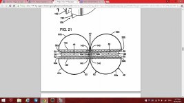
"The diaphragm 46 is preferably constructed of an aramid fiber paper sheet such as Nomex®, produced by duPont, but other flexible, lightweight, high-strength, environmentally stable materials may be used. The central portion 64 of the diaphragm 46 is suspended centrally within the magnet gap 40 by the flexible curved portions 60a, 60b, 62a, 62b. The end of each flexible curved portion is attached adhesively to a respective end portion 30a, 30b, 32a, 32b of each chassis plate 30, 32 so that each flexible portion forms a semi-circular shape, giving the diaphragm the general shape of a figure-eight when viewed from above or below. The curved portions of each web define curved surfaces which extend through respective central apertures 34 to meet at the expanse. The curved portions 60a, 60b, 62a, 62b primarily act as flexible suspension members and not as sound radiating surfaces. This is particularly true at high frequencies, at which only the portions of the diaphragm 46 closest to the center portion 64 are actively radiating sound. Thus, alternate suspension devices may be used without impairing the function of the invention, particularly at high frequencies. FIG. 5 shows the central portion 64 of the diaphragm 46 that resides within the magnetic gap 40. As will be discussed below with reference to FIG. 6, a set of tab portions or tangs 66 are partially cut from the diaphragm 46 and folded perpendicular to the central portion 64 of the diaphragm so that they extend in planes substantially coincident with the exterior surfaces of the pole plates 52, to which the free ends of the tangs 66 are adhesively attached. The central apertures 34 are large enough to expose a sufficiently large area of the exterior surfaces of the pole plates 52 to permit the tangs to be attached thereto. As a result, the central portion 64 is maintained in the central location between the magnets while being free to move laterally within its own plane by a sufficient amount to produce high audio frequencies" (see the attachement from bellow, FIG 21).
Cheers
Sergiu
Attachments
thanks for allthe information, ive read this patent a week back, but its allot to swallow!
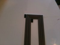
ive done some cuts, like this(around the coil and removed the mid portion) but result was minimal. i would love to do some new tests but not before i got another way of making the coil. since it was a pain in the ***** to make one and i am not content with them. ill be back on monday, and i think i will have something in the mail by then and can start trying to make new coils. only then i can play with the membrame. since when i make a membrame now and cut it up its toast and cant reuse the coil. if i got a flat coil, i could recycle them, and if not, it is at least faster and more consistend way of making a new one.
also i dont want to break any patent of them , i pretty sure i can figure it out without exactly copy them.
I will look into it when i got a good coil setup ! and move on from there. i can even imagine using thinner nomex in the first part of the cylinder then thicker stuff to do the spring. ill order some thinner nomex , since the only stuff i got here in large quantity is 0.25mm thick, i was thinking more in the line of 125 or less. and see what happens. its really stable stuff. as i showed in one of my video;'s trying to kcut it with a drag knife is hard not at all like paper. also you cant rip it at all! just no way of tearing this stuff
Hi Wrinex,
This is the way I make my coils:
I start with a piece of adhesive kapton tape. I stick a strip of the tape upside down on a sheet of glass by sticking the outer perimeter with the same tape.
Cut a piece of layered kapton (x times 0,06 mm) tape with equal thickness of the magnet wire. Use this piece of layered kapton as a core for the coil.
I use “backlack magnet wire” as coil material.
Wrap the wire around the core sticking on the kapton tape.
If I have enough turns of the coil I get a piece of baking paper and another sheet of glass and put it on top of it and bake it in the oven for 20 minutes on 170°C. Know I have my baked coil to use for ???
Maybe an idea for high speed coil production.
Use you router with some pieces of a 3D printer (wire guide), a spool holder, a tensioner as in a sewing machine and a pressure roller to stick the wire on the kapton.
Generate a G-code of a stretched spiral.
There’s your flat coil production machine. (I think)
Regards,
Henjo
This is the way I make my coils:
I start with a piece of adhesive kapton tape. I stick a strip of the tape upside down on a sheet of glass by sticking the outer perimeter with the same tape.
Cut a piece of layered kapton (x times 0,06 mm) tape with equal thickness of the magnet wire. Use this piece of layered kapton as a core for the coil.
I use “backlack magnet wire” as coil material.
Wrap the wire around the core sticking on the kapton tape.
If I have enough turns of the coil I get a piece of baking paper and another sheet of glass and put it on top of it and bake it in the oven for 20 minutes on 170°C. Know I have my baked coil to use for ???
Maybe an idea for high speed coil production.
Use you router with some pieces of a 3D printer (wire guide), a spool holder, a tensioner as in a sewing machine and a pressure roller to stick the wire on the kapton.
Generate a G-code of a stretched spiral.
There’s your flat coil production machine. (I think
)Regards,
Henjo
thanks for allthe information, ive read this patent a week back, but its allot to swallow!
ive done some cuts, like this(around the coil and removed the mid portion) but result was minimal. i would love to do some new tests but not before i got another way of making the coil. since it was a pain in the ***** to make one and i am not content with them. ill be back on monday, and i think i will have something in the mail by then and can start trying to make new coils. only then i can play with the membrame. since when i make a membrame now and cut it up its toast and cant reuse the coil. if i got a flat coil, i could recycle them, and if not, it is at least faster and more consistend way of making a new one.
also i dont want to break any patent of them , i pretty sure i can figure it out without exactly copy them.
I will look into it when i got a good coil setup ! and move on from there. i can even imagine using thinner nomex in the first part of the cylinder then thicker stuff to do the spring. ill order some thinner nomex , since the only stuff i got here in large quantity is 0.25mm thick, i was thinking more in the line of 125 or less. and see what happens. its really stable stuff. as i showed in one of my video;'s trying to kcut it with a drag knife is hard not at all like paper. also you cant rip it at all! just no way of tearing this stuff
Hi Wrine. How's the progress? Have you done the new coils that you where speaking about?
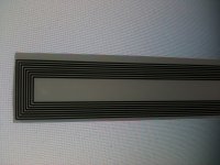
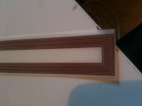
Well a fast test. there is room for smaller spacings. i worked pretty well. although i could not stick a piece of this stuff to a a4 paper and print it. it would always end up half way, with a paper error..... but if i cut a piece and put it in without any paper it does work. i did not remove the ink yet, but you can clearly see its pretty nice. i measured the first one that had some adhesive isues since i did not clean the copper propper and it measured a bit higher then it should 2.9 Ohm instead of the calculated 2.3 i thought i could use 2 in series. but i think ill draw a new one with smaller spacing and slightly smaller traces. to get to 4 ohm.
i even glued it to a piece of 80 grams paper and see what happend. well sensitvity goes up could be because its only a 2.9 ohm load. The high frequencys still falls of but this time not at 13Khz but around 16.5Khz its sounded pretty good. i like the material the copper is on, its sturdy and still not to heavy. so i might take a look at some transperancies for an overhead projector. of around 0.1 mm thick. thats at least 2 times thinner then the Nomex and still can support itself without wrinkling.
and it measured a bit higher then it should 2.9 Ohm instead of the calculated 2.3 i thought i could use 2 in series. but i think ill draw a new one with smaller spacing and slightly smaller traces. to get to 4 ohm.i even glued it to a piece of 80 grams paper and see what happend. well sensitvity goes up could be because its only a 2.9 ohm load. The high frequencys still falls of but this time not at 13Khz but around 16.5Khz its sounded pretty good. i like the material the copper is on, its sturdy and still not to heavy. so i might take a look at some transperancies for an overhead projector. of around 0.1 mm thick. thats at least 2 times thinner then the Nomex and still can support itself without wrinkling.
Attachments
Hi Wrine,
Congratulations. That's really nice. Now you can see what happends with the perforations on the coil if you want to experiment more..
But how about sensitivity? How much SPL did you measured now?
Have you tried thinner traces for higher impedances on the coil?
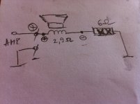
What do you say if you put in series a 6ohm/20W resistor to have aprox 8 ohm, between (-) of the speaker and ground (like in the photo attached)? This way the resistor will not cut the high frecvencies.
Anybody measured or simulated this before?
I did something like this in a similar situation, but in my case the speaker was an 8 inch, 2.4 ohm bass speaker, not a fullranger like in this speaker's case..
Cheers
Sergiu
Congratulations. That's really nice. Now you can see what happends with the perforations on the coil if you want to experiment more..
But how about sensitivity? How much SPL did you measured now?
Have you tried thinner traces for higher impedances on the coil?
What do you say if you put in series a 6ohm/20W resistor to have aprox 8 ohm, between (-) of the speaker and ground (like in the photo attached)? This way the resistor will not cut the high frecvencies.
Anybody measured or simulated this before?
I did something like this in a similar situation, but in my case the speaker was an 8 inch, 2.4 ohm bass speaker, not a fullranger like in this speaker's case..
Cheers
Sergiu
Attachments
Hello my friend Wrine,
Today i placed an order for the magnets. I'm not ordering any more the 40*10*10 ones, instead i ordered 40*20*10 N42 Neo magnets.
I'm still confused about this 1018 steel (A37 in France). Does anyone know an European (romanian) equivallent for this steel?
Please help!
I'm trying desperatelly to find a source. I'm searcing on the web but still nothing.
The rest is peace of cake (aluminium bars, fasteners) because i work at a warehouse..
Thanks
Sergiu
Well a fast test. there is room for smaller spacings. i worked pretty well. although i could not stick a piece of this stuff to a a4 paper and print it. it would always end up half way, with a paper error..... but if i cut a piece and put it in without any paper it does work. i did not remove the ink yet, but you can clearly see its pretty nice. i measured the first one that had some adhesive isues since i did not clean the copper propper
i even glued it to a piece of 80 grams paper and see what happend. well sensitvity goes up could be because its only a 2.9 ohm load. The high frequencys still falls of but this time not at 13Khz but around 16.5Khz its sounded pretty good. i like the material the copper is on, its sturdy and still not to heavy. so i might take a look at some transperancies for an overhead projector. of around 0.1 mm thick. thats at least 2 times thinner then the Nomex and still can support itself without wrinkling.
After i studyed again the patents i fugured out another interesting thing:
-the high frecvencies are all comming from the lateralls of the cilinders and from the center of the coil.
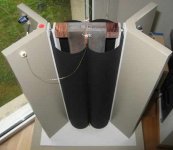
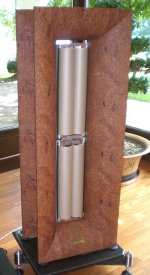
If we beam the sound, speacially hights with two V shape materials only on the laterall of the cilinders (like in the first picture from bellow, left syde) we actually beam only the "weaker" high frecvencies but what about the ones that are coming from the interior of the coil, in our case from the interior of the cilinders? I think that we also need V shape lateralls above and bellow the cilinders to beam the "strong" (more powerful) hights from the interior of the cilinders.
After surfing the web for more details about my theory i found that the clever guys from AudioNec allready figured this out. Look at the picture nr 2 from bellow (from the right) and you will see what i mean.
I'm not trying to reinvent the weel here, i want to point some subtle clever solutions that i digged on the web for the "hights problem" that you have Wrine.
Cheers
Sergiu
Attachments
Last edited:
- Home
- Loudspeakers
- Planars & Exotics
- A DIY Ribbon Speaker of a different Kind