Hi
I simulated only output stage and found that THD is poor, at about -80dB
at 4Vrms
but maybe nfb helps it shine?

Hi Ken,
I don't understand how it could be thermaly stable in AB class, maybe in A class??
Could you elaborate how the bias could be stable without thermal connection with output transistors.
dado
Dado,
I've been using the amp for over a year and haven't had a problem. The main thing is that I think it seldom goes into Class B except for very loud music passages or things like drum or cannon shots... Your point has me thinking that it would be good practice to devize something to help with this issue like the thermistors that are used on the F5. I will look into this.
Ken
Hi
I simulated only output stage and found that THD is poor, at about -80dB
at 4Vrms
but maybe nfb helps it shine?
I've simulated it every way you can imagine with lots of suggestions from Keantoken. In some simulations the THD was .00000%. I finally resorted to apending it to a working amp model to fully understand how it behaves relative VAS loading and overall feedback.
Ken
I've simulated it every way you can imagine with lots of suggestions from Keantoken....Ken
Hi
the simulation of whole amp showed very low thd indeed, in my simulator bb2 spice
if you want to play with your design,
try lower emiter resistor values R16,18 down to 10 or even 0 ohms,
thd will be better at about 20dB
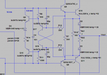
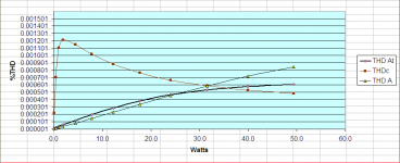
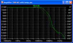
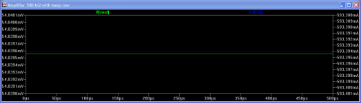
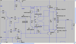
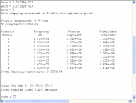
I've looked at a strategy for thermal compensation. Inserting a diode between Q9 and Q10 and tying this diode to the output transistors, the bias tracks down slightly as the amp heats up. At 50watts out, and all devices at 25c the current across Re is 2.5A. With output devices at 55c, the current across Re is 1.9A. Schematic is attached along with the prior graph with a new line showing the effect of the new diode and output devices running at 55c.
Attachments
Hi, klewis, What are the THD's at mid output power for 10KHZ 20KHZ and 100KHZ? What's the HI-FI BW?
Cheers
Arturo
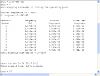
Arturo,
At 10v out.
Ken
Attachments

THD refinement
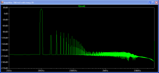
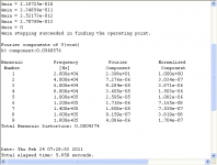
Ken, That are very good numbers !!!, I also achieved similar results with a full symmetric complementary topology and found that besides the low THD also has a very nice harmonic distribution, (see the pix) I should test your VAS with my topology, maybe it performs better than mine.
Cheers
Arturo
Ken, That are very good numbers !!!, I also achieved similar results with a full symmetric complementary topology and found that besides the low THD also has a very nice harmonic distribution, (see the pix) I should test your VAS with my topology, maybe it performs better than mine.
Cheers
Arturo
Attachments
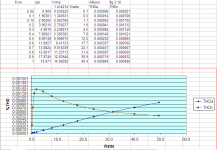
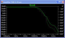
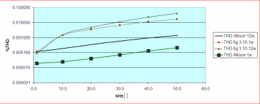
I implemented what Bob Cordell calls bridged T compensation (BTC) on both the fig 3.10 baseline amp and the modified Allison with the thermal compensation. I ran THD numbers at 1k, 10k, 20k, 30k, 40k, 50k at 1 and 12 watts out. The graph below tells the story.
Attachments


 After trying the BTC compensation I then tried TMC on both fig 3.10 and the Allison. fig 3.10 with TMC at 1khz blew the Allison away... I must say I was disappointed in the Allison. Each of the prior improvements to the front end resulted in the both the amps improving in parallel, with the Allison always being the better amp (at least in simulation). I must also admit that I haven't tried or listened to a TMC amp.
 So, here is a summary of the THD figures for all three version of the fig 3.10 amp and the Allison with TMC at 1kHz. I've made a few tweaks of the Allison as well and will post that later. The story will continue in the next post.
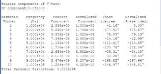
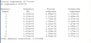
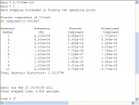
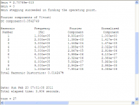
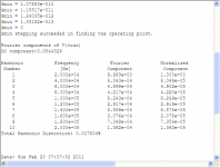
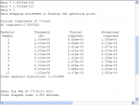
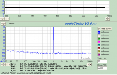
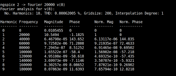
The first fft is the fig 3.10 TMC amp and the second is the Allison TMC amp - both at 1kHz.
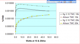
Struggling with my disappointment, and after trying to decide if the Allison is a dead end I thought I should look at the 10kHz and 20kHz THD for both amps. Well, these results cheered me up a bit. The Allison's performance doesn't change much at all as the frequency goes up, while fig 3.10 deteriorates rather dramatically as the frequency increases. I don't know, maybe everybody here knew this already, but, it was a surprise to me. Maybe it's not audible... I know now that I will have the fig 3.10 TMC and compare it to the Allison.
The following is the THD comparisons of the fig 3.10 TMC vs the Allison TMC at 10 and 20kHz the ffts for both at the same frequencies (the fig 3.10s first, the Allison second.
, and after trying to decide if the Allison is a dead end I thought I should look at the 10kHz and 20kHz THD for both amps. Well, these results cheered me up a bit. The Allison's performance doesn't change much at all as the frequency goes up, while fig 3.10 deteriorates rather dramatically as the frequency increases. I don't know, maybe everybody here knew this already, but, it was a surprise to me. Maybe it's not audible... I know now that I will have the fig 3.10 TMC and compare it to the Allison. The following is the THD comparisons of the fig 3.10 TMC vs the Allison TMC at 10 and 20kHz the ffts for both at the same frequencies (the fig 3.10s first, the Allison second.
Attachments
Struggling with my disappointment
Hi!
for me Allison version blewed up 3.10
those sim results look outstanding.
to indicate the winner
please show sim results 20kHz close from clipping
what is idle current of output transistors?
Hi!
for me Allison version blewed up 3.10
those sim results look outstanding.
to indicate the winner
please show sim results 20kHz close from clipping
what is idle current of output transistors?
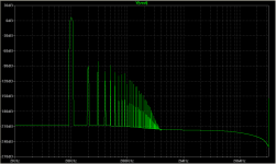
Hi Padamiecki,
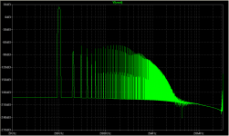
I've attached results for the Allison at 20kHz close to clipping. Also attached my simulation file. You will need Bob Cordell's models, which come with his simulation files. Down-loadable from his web site.
R14 sets the idle current.
I will run the same for the fig 3.10 tonight.
Ken
Attachments
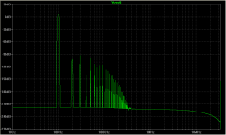
Here are the results for the fig 3.10 amp with TMC at 20kHz close to clipping.
hm
Allison beats 3.10

and the higher harnonics are like nongnfb designs...
Other THD factors
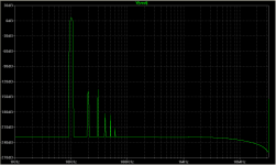
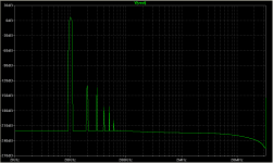
Hi Ken,
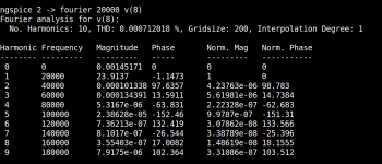
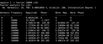
To be fair we must compare apples to apples. Indeed this (allison) VAS topology is far better than 3.10, but when dealing with very low distortion I've founded that the choice of buffer+power output devices (all the rest equal) dominates the very small levels and shape of higher harmonics, ie, (even with very high OLG's) I've found that a single replacement at the buffer of mje340/350 by the old BD139/140 lowers the higher harmonics by a factor of 5, MJE340/350 first pix, BD139/140 second pix. Same applies with the OPT devices.
Cheers
Arturo
Hi Ken,
To be fair we must compare apples to apples. Indeed this (allison) VAS topology is far better than 3.10, but when dealing with very low distortion I've founded that the choice of buffer+power output devices (all the rest equal) dominates the very small levels and shape of higher harmonics, ie, (even with very high OLG's) I've found that a single replacement at the buffer of mje340/350 by the old BD139/140 lowers the higher harmonics by a factor of 5, MJE340/350 first pix, BD139/140 second pix. Same applies with the OPT devices.
Cheers
Arturo
Attachments
- Status
- This old topic is closed. If you want to reopen this topic, contact a moderator using the "Report Post" button.
- Home
- Amplifiers
- Solid State
- A different CAS typology with very low THD