Bandwidth, symmetrical slew, graceful clipping, THD at low and medium levels:
All of great importance. Forced low THD at highest output levels maybe not.
Nothing like when an absolute current or voltage linearity hits a brick wall...
Trying too hard for an impossibly low THD makes other problems unsolvable.
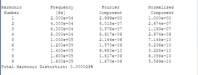
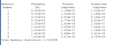
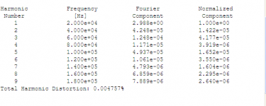
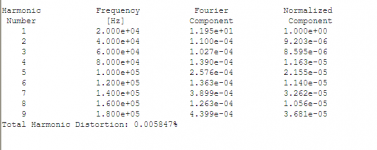
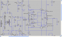
Back to Bob Cordell's criteria, quite similar to KenPeter's. I think I showed graceful clipping in some prior posts. Now for 20kHz thd numbers at low power (1watt) and medium power (18watts) with declining H2 throught H9 numbers. Again the Allison variant vs the Fig 3.10 both with TMC implemented, also Allison with smaller value vas emitter degen resistors, /lower noise. image 1 Allison 20khz 1watt, #2 Allison 20khz 18 watt, #3 Fig 3.10 20khz 1watt, #4 Fig 3.10 20khz 18watt
Ken L
Attachments
klewis ...
arturo,
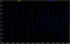
just for fun the first 10ms of Wagner Siegfried .wav file.
Hi Ken, believe or not it's a good test, it showed me many 'apparently' good amp failing at the trebles, it is a simple and effective method (do the same test at 10x freq.). For me your numbers are more than enough, and Class AB helps a lot to enhance the harmonic profile and maintain low IMD products, it would be desirable to know the slew rate and the power bandwidth, there are several issues that you know simms don't reveal, thermal and bias stability, insidious HF oscillations, start up transient, undesirable interactions with the PSU and speakers ... etc, all to be resolved tuning the physical prototype.
Cheers
Arturo
Arturo,Hi Ken, believe or not it's a good test, it showed me many 'apparently' good amp failing at the trebles, it is a simple and effective method (do the same test at 10x freq.). For me your numbers are more than enough, and Class AB helps a lot to enhance the harmonic profile and maintain low IMD products, it would be desirable to know the slew rate and the power bandwidth, there are several issues that you know simms don't reveal, thermal and bias stability, insidious HF oscillations, start up transient, undesirable interactions with the PSU and speakers ... etc, all to be resolved tuning the physical prototype.
Cheers
Arturo
So, how to I determine the slew rate and power bandwidth?
Ken
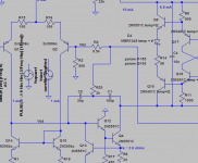
KenPeter commented on feeding the signal between the emitters. I went back and looked at my notes. What I found was that I had a lot of issues with other things going on at the time (such as transistor selection), so, between the emitter has potential in this configuration. It's not throughly tested... here is my implementation of applying the signal between the emitters. Not sure about the temp compensation diode in this location, but, the thd numbers at 20khz 1watt and 18watts are better than the prior post.
Ken L
Ken L
Attachments
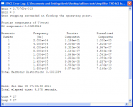
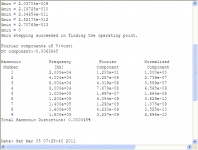
Back to the prior allison scheme, I just noticed that I had my TMC set a bit high 60pf 2k 300pf, changed it to 30pf 1k 150pf got the following THD at 20kHz 18watts ")
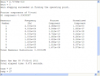
Did the same with the between the emitters scheme from the prior post. that 's the third image.
KenL
Did the same with the between the emitters scheme from the prior post. that 's the third image.
KenL
Attachments

square 100KHZ
about slew rate:
I use a square at 100KHZ very high dv/dt at input like this:
vin 100 0 DC 0 PULSE(-1.5 1.5 0 .00000000001 .00000000001 .00000499999 .00001)
beware to bypass any input cap. (and decoupling cap. to GND at the NFB if exists), the -1.5 and 1.5 levels should be adjusted to a just before clipping level (or lower) and you should see at the output something like the pix. The slew rate is the slope from 10% to 90% of the amplitude of the leading edge, and the slope of the trailing edge, usually the later is greater. This test will reveal if there is any dv/dt induced instability (ringing).
Cheers
Arturo

Yes ..klewis ...
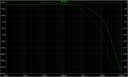
Is this bandwidth?
about slew rate:
I use a square at 100KHZ very high dv/dt at input like this:
vin 100 0 DC 0 PULSE(-1.5 1.5 0 .00000000001 .00000000001 .00000499999 .00001)
beware to bypass any input cap. (and decoupling cap. to GND at the NFB if exists), the -1.5 and 1.5 levels should be adjusted to a just before clipping level (or lower) and you should see at the output something like the pix. The slew rate is the slope from 10% to 90% of the amplitude of the leading edge, and the slope of the trailing edge, usually the later is greater. This test will reveal if there is any dv/dt induced instability (ringing).
Cheers
Arturo
Last edited:
How big must the slew rate be....?? I just simulated my complete amplifier and got this result....looking at the output i believe my amplifier slews at app 70V/us...and does so with out any over shoot or ringing....I have no idea on how that is in comparison with other designs as this type of simulation is new to me. I have in the feedback a small capacitor parallel over the FB resistor.. in this simulation its 2.2 pF if i change that to 1pF the top corner becomes at little sharper.. and by removing it a little ringing starts to appear...when ringing the feedback currents become very spiked...so there must be some fine balance there....
BTW it's the complete amplifier and not the CAS alone
BTW it's the complete amplifier and not the CAS alone
Attachments
Last edited:
How big must the slew rate be....??
Nobody knows for sure.
Hi,t....looking at the output i believe my amplifier slews at app 70V/us...............
............. I have in the feedback a small capacitor parallel over the FB resistor.. in this simulation its 2.2 pF if i change that to 1pF the top corner becomes at little sharper.. and by removing it a little ringing starts to appear...when ringing the feedback currents become very spiked...so there must be some fine balance there....
Artu's slew rate looks like ~58Vpp in 0.4us, i.e. ~145V/us.
Mib's slew rate looks like ~60Vpp in 1us, i.e. ~60V/us.
The parasitic capacitances can approach and even exceed 1p or 2pF.
Try increasing the parasitics in various location where traces or wires are near each other and see how clean the simulation remains. You may find that some locations are very tolerant of parasitics, whereas other locations respond (badly) to tiny capacitance/inductance.
I've seen suggestions that Slew that allows full power at 20kHz is never going to be used with real music.
I've also seen suggestions that slew rate equivalent to full power at 10 times 20kHz is a sensible target to aim for.
I think that confirms there is much to argue about.
Last edited:
NE5534 has 6V/uS with Cc=22pf and 13V/uS without Cc. It sounded better with Cc.
Some Amp with >50V/uS slewrate has bad treble and ugly bass also nasty midle. Because they designed to reach 100V/uS slewrate, and not designed to have good sounds.
Add: from the name, VAS should be dV/dt with cap load depend on its current capability and CAS dI/dt, inductor load depend on its voltage capability. But everyone measure it with resistor load and dV/dt.
Hi, ken, better not using TMC, I found this thing is bad in multi tone.
Last edited:
Thanks Andrew for putting some perspective on this...!!
Just ran 200 KHz through at +/-55 V out... Distortion is still quite low..0.05%..and still mainly second order...looking at the maximum slew rate of the 200 KHz sine wave at +/-55 Volts it's app 55V/us and thus approaching the simulated slew rate limit in the circuit..
The needed slew for practical music.. I don't know.. some of the best amplifiers I have ever heard are tube based...and playing through a transformer..where the power bandwidth is severely limited.. often to less than 40KHz...but boy could they sing...
Last edited:
- Status
- This old topic is closed. If you want to reopen this topic, contact a moderator using the "Report Post" button.
- Home
- Amplifiers
- Solid State
- A different CAS typology with very low THD