heheh! It is "hawksford's error correction".Now my turn, what is HEC?
Hi Ken,
The BD models used are from Fairchild,
.MODEL qBD139f NPN (IS=2.3985E-13 BF=244.9 NF=1.0 BR=78.11 NR=1.007
+ ISE=1.0471E-14 NE=1.2 ISC=1.9314E-11 NC=1.45 VAF=98.5 VAR=7.46 IKF=1.1863 IKR=0.1445
+ RB=2.14 RBM=0.001 IRB=0.031 RE=0.0832 RC=0.01 CJE=2.92702E-10 VJE=0.67412 MJE=0.3300
+ FC=0.5 CJC=4.8831E-11 VJC=0.5258 MJC=0.3928 XCJC=0.5287 XTB=1.1398 EG=1.2105 XTI=3.0
)
.MODEL qBD140f PNP (IS=2.9537E-13 BF=201.4 NF=1.0 BR=23.765 NR=1.021
+ ISE=1.8002E-13 NE=1.5 ISC=7.0433E-12 NC=1.38 VAF=137.0 VAR=8.41 IKF=1.0993 IKR=0.10
+ RB=1.98 RBM=0.01 IRB=0.011 RE=0.1109 RC=0.01 CJE=2.1982E-10 VJE=0.7211 MJE=0.3685
+ FC=0.5 CJC=6.8291E-11 VJC=0.5499 MJC=0.3668 XCJC=0.5287 XTB=1.4883 EG=1.2343 XTI=3.0
)
Cheers
Arturo
Hawksford's won't much help reducing error caused by supply ripple, output switching(crossover), output lags, capacitive load and such errors that are dominating in designing amplifiers, non linearity error is just simple thing to handle. The best one is negative feedback EC. It handle every kind of errors.
Added: Could you umm.. using classB or AB like thanh also asked. It will more interested, because everything is getting easy in classA with regulated supply(with no ripple and shaking rail), you don't need error correction in classA, and it will still very good.
Added: Could you umm.. using classB or AB like thanh also asked. It will more interested, because everything is getting easy in classA with regulated supply(with no ripple and shaking rail), you don't need error correction in classA, and it will still very good.
Last edited:
heheh! It is "hawksford's error correction".
This configuration looks quite similar to HEC. Here it's called Allison. There is a bit more on the Allison configuration do a search for "Simulation Allison" and you will find Keantokens original thread.
I believe you asked how to calculate the resistor values for HEC. The one resistor R14 in this circuit between the two Allison transistors Q8/Q10. I set the value of R14 by trial and error based upon the size of heat sink that I have. The smaller the value of R14, the lower the bias of the output transistors. For my set up, my heat sinks can handle a bias of about 500mA at each device. The heat sinks are about 8 inches square with 2 inch fins. For the simulations that I have been working with here, I've been using this 500mA bias or about 24watts as measured in simulation at the output devices.
Here I see Schottky crossings and good stuff.
I had no idea anyone was even paying attention.
Can you post the latest .asc as .txt or .zip ?
KenPeter,
Nice to see you again. I'll post the latest tonight.
Ken
Hi Ontoaba
Not completely agree, maybe Class A AB helps (at the high spectrum H products), but it is not merely doing a huge OLG amp with NFB to be done, not that easy, there is the PSU, BW & slew, noise, thermal stability, output impedance, clipping ... and several other issues that makes some topologies perform better than others, given a set of devices. A key factor for achieving low distortion is undoubtedly the VAS, and the 'allison' VAS (which is not HEC) may pay the extra complexity with better 'sound', I guess.
Ken, I would like to see other characteristics of your amp such as clipping, settle-time transient, thermal drift, behaviour with capacitive & inductive loads, premises of design you had in mind ... or any other useful information.
Cheers
Arturo
Hawksford's won't much help reducing error caused by supply ripple, output switching(crossover), output lags, capacitive load and such errors that are dominating in designing amplifiers, non linearity error is just simple thing to handle. The best one is negative feedback EC. It handle every kind of errors.
Added: Could you umm.. using classB or AB like thanh also asked. It will more interested, because everything is getting easy in classA with regulated supply(with no ripple and shaking rail), you don't need error correction in classA, and it will still very good.
Not completely agree, maybe Class A AB helps (at the high spectrum H products), but it is not merely doing a huge OLG amp with NFB to be done, not that easy, there is the PSU, BW & slew, noise, thermal stability, output impedance, clipping ... and several other issues that makes some topologies perform better than others, given a set of devices. A key factor for achieving low distortion is undoubtedly the VAS, and the 'allison' VAS (which is not HEC) may pay the extra complexity with better 'sound', I guess.
Ken, I would like to see other characteristics of your amp such as clipping, settle-time transient, thermal drift, behaviour with capacitive & inductive loads, premises of design you had in mind ... or any other useful information.
Cheers
Arturo
Hi Artu,
Topologies. That's true dominating, but classA always best and easier to be linearized than cassAB or B. It is impossible to use huge NFB with long chain stages from input to output stages. The NFB could be used in output stage only to get lowest error from the output comparing with VAS output.
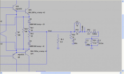
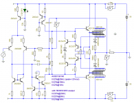
This one for example: Using two negative feedback. Fist feedback working in high speed and the second help it. ClassAB and HEXFET, still very stable with very good error correction from output and supply.
May be this picture should posted there: (they also using Hawksford's) http://www.diyaudio.com/forums/solid-state/182663-fast-simple-driver-hexfets-linear-use.html
I feel its ok to post it here.
Topologies. That's true dominating, but classA always best and easier to be linearized than cassAB or B. It is impossible to use huge NFB with long chain stages from input to output stages. The NFB could be used in output stage only to get lowest error from the output comparing with VAS output.
This one for example: Using two negative feedback. Fist feedback working in high speed and the second help it. ClassAB and HEXFET, still very stable with very good error correction from output and supply.
May be this picture should posted there: (they also using Hawksford's) http://www.diyaudio.com/forums/solid-state/182663-fast-simple-driver-hexfets-linear-use.html
I feel its ok to post it here.
Attachments
Hi Ontoaba
Ken, I would like to see other characteristics of your amp such as clipping, settle-time transient, thermal drift, behaviour with capacitive & inductive loads, premises of design you had in mind ... or any other useful information.
Cheers
Arturo
How do you simulate clipping behavior? I can certainly over drive the simulation Vin, but how do you look at clipping recovery? Same for settle-time transient and thermal drift. I can figure out the others.
Regards,
Ken
Hi, Klewis, I post my VAS here may be you need different VAS.
http://www.diyaudio.com/forums/soli...erformance-never-let-me-down.html#post2488064
http://www.diyaudio.com/forums/soli...erformance-never-let-me-down.html#post2488064
Hi, Klewis, I post my VAS here may be you need different VAS.
http://www.diyaudio.com/forums/soli...erformance-never-let-me-down.html#post2488064
Hi ontoaba,
I think my VAS is doing pretty well... have you seen post #47?
KenL
Ken, I would like to see other characteristics of your amp such as clipping, settle-time transient, thermal drift, behaviour with capacitive & inductive loads, premises of design you had in mind ... or any other useful information.
Cheers
Arturo
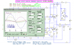
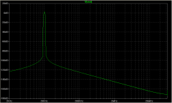
Here is performance into a complex load - Sigfrid Linkwitz (spelling?) values for an 8ohm speaker. First, 1watt 1kHz, 1watt 20kHz FFT, 1watt 20kHz THD and 50watt 20kHz THD and FFT.
KenL
Attachments
Last edited:
But my simulation results only 0.02%THD, may be caused by the output transistor or something. I don't have those output BJT here, and entering model to the table will need much time.
I see your NJL3281 with 438 forward beta, is that correct?
And when I using TIP3055/2955, they may blow when hard clip happen at 10kHz and up. Not happened to all BD139/140, they are fast.
I see your NJL3281 with 438 forward beta, is that correct?
And when I using TIP3055/2955, they may blow when hard clip happen at 10kHz and up. Not happened to all BD139/140, they are fast.
Attachments
clipping issue
Hi Ken,
I use a similar 'complex load' more or less a speaker model, that's fine, I usually put a pure 100 nf and 2uF capacitive loads (both seems to be nasty) and test the amp just before clipping and clipping at very high freq. >= 100KHZ (much as slew allows, but bellow) and look at the falling edge when the amp re enters the linear region to verify if there is a sign of ringing. Also it is important that the DC offset do not deviate to much from 0 (symmetric clipping), that can be verified doing a fourier analysis (DC component). Other test is the square wave with very high dv/dt I use:
vin 100 0 DC 0 PULSE(-1.5 1.5 0 .00000000001 .00000000001 .00000499999 .00001)
a 100KHZ,
inspecting the wave at the VAS you can check the settle time, the time that the VAS takes to stabilize after the leading and falling edge transient. Also test the square wave with the nasty load of above (the load will resonate, but the amp should maintain a stiff drive).
Cheers
Arturo
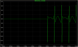
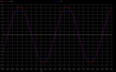
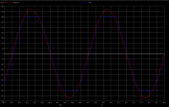
Clipping examples
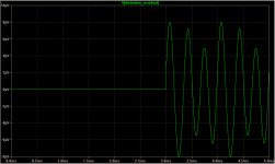
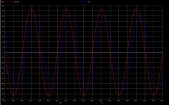
The red trace is the input signal multiplied by the amp gain a 'control reference', and the blue trace is the output signal, at 20KHZ, 100KHZ, 500KHZ
Cheers
Arturo
The red trace is the input signal multiplied by the amp gain a 'control reference', and the blue trace is the output signal, at 20KHZ, 100KHZ, 500KHZ
Cheers
Arturo
Attachments
Ahh.. your simulation is not going right. 2n3906 as input can not do that good, it only fast.
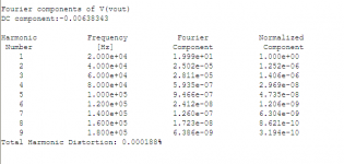
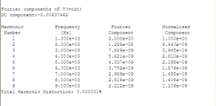
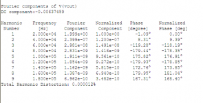
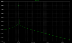
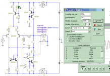
Here my simulation with original model. Results only 0.004% THD at 1kHz, while my VAS has 0.0002% THD at 10kHz.
How could you get such linearity with bad VAS linearity huh?.
Do not trust your sim results, they are not going right.
Here my simulation with original model. Results only 0.004% THD at 1kHz, while my VAS has 0.0002% THD at 10kHz.
How could you get such linearity with bad VAS linearity huh?.
Do not trust your sim results, they are not going right.
Attachments
Last edited:
- Status
- This old topic is closed. If you want to reopen this topic, contact a moderator using the "Report Post" button.
- Home
- Amplifiers
- Solid State
- A different CAS typology with very low THD