Tried some fiddling around measurements and determining acoustic offsets. What really got me forward, though, was realizing that the woofer's SPL cuts out as if it was filtered with a 3rd degree XO, even though the actual circuit is only an inductor, and parallel with the XO there's also a series RLC circuit to kill resonances.
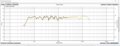
So, I tried a 3rd degree filter for the tweeter. After simulating some options, trying one out, and adjusting some more, I ended up with this (image 1: measurement in a small room). The 3rd degree XO also allowed me to cross a little lower for more constant driver directivity and use two RLC circuits in parallel to kill those break-off resonances (image 2: WinISD simulation).
My only real grievance right now is that dip at 7-9 kHz. Not sure how it could be dealt with.
Edit: I also added a RL contour filter to deal with hte baffle step.
Attachments
Last edited:
You'll still want to go through a process of 'voicing'. This is where you discover whether a 'flat' response is what you want.. ie taking into consideration the fact that dispersion is falling for the tweeter toward the top end despite the response appearing flat, due mostly in this case to its size and maybe its breakup region.
When you design a crossover using a single response measurement per driver it is usually best to keep clear of the breakup region at a woofers top end to avoid the complication, and not to get too caught up on the large peak that some woofers show.
When you design a crossover using a single response measurement per driver it is usually best to keep clear of the breakup region at a woofers top end to avoid the complication, and not to get too caught up on the large peak that some woofers show.
Gah! It's too bright! ")
Point the tweeter down, not flat unless you are listening in a well damped room or outside.
If you find yourself making 2 notch filters for the woofer, it may be you need a Zobel instead to help make the roll off more consistent.
Also with all the EQ'ing going on, keep an eye on your overall impedance graphs.
Best,
Erik
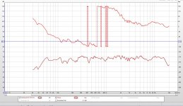
Adjusted by the mic manufacturer's frequency response curve, the current design would look like this (image 1). The mic's curve is the black one. That's why I tried an overly bright design at first. The current design sounds quite balanced by my ear though, and I have tried some some less bright designs before with these speakers. Haven't calibrated the mic, so the truth is probably something in between or so. Anyways, I can't be sure, so ultimately I'll have to go with what pleasures my ear.
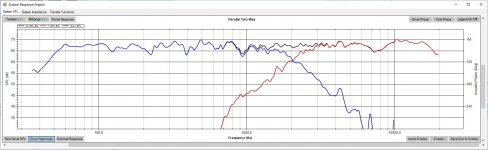
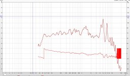
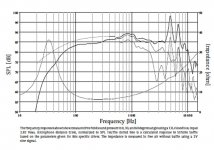
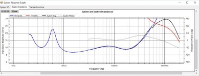
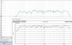
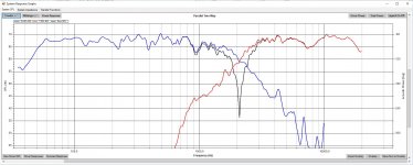
With the XO I tried a nice traditional zobel at first, but I ended up with using two notch filters. The notch filters also take the overall SPL down quite much. So much actually, that the woofer roll-off seems like through a 3rd degree filter. The manufacturer spec sheet (image 3) and my own measurement of the woofer (image 2) should tell why I was so adamant taking on the resonances. The resonances could be otherwise fine, lost in the overall and killed by the tweeter in opposite phase, but the resonances really come up at 60 degrees off axis where high frequencies have otherwise gone down, so one would get nasty spikes at 5 and 7 kHz off axis if they weren't dealt with.
With the XO I tried a nice traditional zobel at first, but I ended up with using two notch filters. The notch filters also take the overall SPL down quite much. So much actually, that the woofer roll-off seems like through a 3rd degree filter. The manufacturer spec sheet (image 3) and my own measurement of the woofer (image 2) should tell why I was so adamant taking on the resonances. The resonances could be otherwise fine, lost in the overall and killed by the tweeter in opposite phase, but the resonances really come up at 60 degrees off axis where high frequencies have otherwise gone down, so one would get nasty spikes at 5 and 7 kHz off axis if they weren't dealt with.
Attachments
Last edited:
I suspect the peak in the impedance is the 7K notch. I hadn't noticed the 2.6 ohms in series with the woofer before. Without it the impedance would drop to around 2.5 ohms?? are you paralleling up drivers? The nominal impedance on the woofers is 8 ohms, so if you are not then it looks like something is wrong with your impedance measurements.
My MTM's are about 3 ohms at their lowest, which worried me at first, but I've had no problem driving them with my mosfet amp, or my LM3886 based amp.
Tony.
My MTM's are about 3 ohms at their lowest, which worried me at first, but I've had no problem driving them with my mosfet amp, or my LM3886 based amp.
Tony.
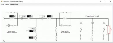
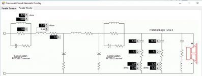
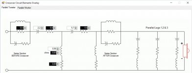
Here are the current crossovers. The WinPCD schematics are a bit messy, sorry about that. They show all the "possible" components (i.e. those that WinPCD can calculate), but only the "active ones" i.e. those with values attached to them are actually there.
Attachments
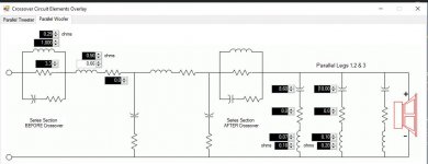
So there's an RL contour filter before the woofer crossover to handle baffle step. Then there are two RLC notch filters to handle break off resonances. Thirdly, there's a parallel 22 ohm resistor to even the woofer impedance spikes at low frequencies. That's what takes the impedance so low at 140 Hz. I don't think there's any real use in evening the impedance at low frequencies, so I think I'll get rid of that resistor. Impedance without the resistor should look like this (image).
Attachments
And also, the speaker (the one i have with the new crossover) is still a bit too bright, now that I've listened to it a bit. You were right.
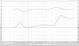
I'm thinking of losing the parallel resistor from the woofer section. It would give me a bit more sub 1 kHz frequencies with a bit higher impedance. In the image attached: the current design (in yellow) and overlaid a design without the resistor (in black).
I'm thinking of losing the parallel resistor from the woofer section. It would give me a bit more sub 1 kHz frequencies with a bit higher impedance. In the image attached: the current design (in yellow) and overlaid a design without the resistor (in black).
Attachments
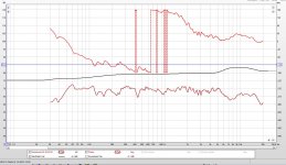
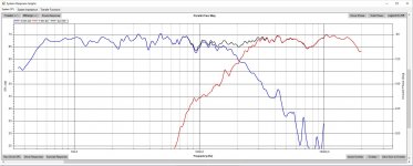
Tried yet a couple different configurations. I'm liking what I'm hearing currently! It is quite hot at mid range, but when I tried with lower mids it sounded a bit muffled to my ear. The measurement doesn't quite match the WinPCD simulation even if I try playing around with acoustic offset (Image 1: comparison, measurement above and simulation below). I don't mind though, for I intend to keep this configuration for now.
The measurement was made in a small room, speaker on a low stand (i.e. a chair), mic 70 cm from baffle at tweeter axis, tweeter and mic 92 cm above floor. There's a pillow on the floor between the speaker and the mic to mitigate floor reflections. 1/24 octave smoothed.
The room I'm listening in is pretty small, so modal frequencies give quite aggressive a boost to bass, especially around 60 Hz. Maybe that's why the mid range hot response sounds good to my ears.
Tweeter and woofer crossovers are shown in images 2 and 3.
The measurement was made in a small room, speaker on a low stand (i.e. a chair
), mic 70 cm from baffle at tweeter axis, tweeter and mic 92 cm above floor. There's a pillow on the floor between the speaker and the mic to mitigate floor reflections. 1/24 octave smoothed.The room I'm listening in is pretty small, so modal frequencies give quite aggressive a boost to bass, especially around 60 Hz. Maybe that's why the mid range hot response sounds good to my ears.
Tweeter and woofer crossovers are shown in images 2 and 3.
Attachments
What I'm liking by ear is the off axis response. I don't hear any dips or other sudden changes in sound stage when i move around the room (save the modal frequencies). I'll take some off axis measurements in a few days to actually see what the off axis response looks like. In theory it should be quite good, for the current XO point at 2000 Hz is a couple hundred Hz below the point where the woofer's directivity goes up.
Also, as far as the WinPCD simulation (and my .frd files) are correct, driver phases seem really nicely aligned (image 1 of WinPCD simulation with normal tweeter polarity and image 2 with polarity reversed). As I mentioned earlier, the simulation doesn't quite match the measurement though.
I don't think I'll measure the tweeter polarity effect in real life for now, for it'd require a soldering iron, a screwdriver and a bit too much work for just the sake of finding out.
Also a note to myself: when trying to get a crossover to work, breadboard assembly would be nice! When I started, the speakers were already fully assembled and it was merely about broken woofer replacement. When the original woofer wasn't available, it gradually became a crossover design project. When I started, I only had a faint idea of what crossovers do in general, and so for the past few months the learning curve has been steep.
Every gradual change toward better results was a "this is it" moment. So..
Because of basic human stupidity I never fully disassembled the crossovers to have a clean slate with a breadboard.
My newly bought cheapo soldering iron and glue gun have seen some pretty heavy use recently, for I've had had to disassemble the soldered crossover network and glued on components every time I made a change, not to mention the speaker boxes with back plates assembled with 10 or so screws and so on..
Well, this is my first real speaker project, for when I originally assembled the speakers, I just used a ready made design. It is of course possible I'll be making again "some minor changes" to the crossovers in no time.
Also, as far as the WinPCD simulation (and my .frd files) are correct, driver phases seem really nicely aligned (image 1 of WinPCD simulation with normal tweeter polarity and image 2 with polarity reversed). As I mentioned earlier, the simulation doesn't quite match the measurement though.
I don't think I'll measure the tweeter polarity effect in real life for now, for it'd require a soldering iron, a screwdriver and a bit too much work for just the sake of finding out.
Also a note to myself: when trying to get a crossover to work, breadboard assembly would be nice!
When I started, the speakers were already fully assembled and it was merely about broken woofer replacement. When the original woofer wasn't available, it gradually became a crossover design project. When I started, I only had a faint idea of what crossovers do in general, and so for the past few months the learning curve has been steep.Every gradual change toward better results was a "this is it" moment. So..
Because of basic human stupidity I never fully disassembled the crossovers to have a clean slate with a breadboard.
My newly bought cheapo soldering iron and glue gun have seen some pretty heavy use recently, for I've had had to disassemble the soldered crossover network and glued on components every time I made a change, not to mention the speaker boxes with back plates assembled with 10 or so screws and so on..
Well, this is my first real speaker project, for when I originally assembled the speakers, I just used a ready made design. It is of course possible I'll be making again "some minor changes" to the crossovers in no time.
Attachments
Last edited:
I'm also considering a slight adjustment to the reflex port/tube. I get a feeling that lower (perhaps <40 Hz) bass frequencies distort a bit too much. Most likely the port is too narrow (43 mm inner diameter) and the fast airflow causes distortion. This tube (pvc tube for plumbing) was the only thing that was feasibly available for me at the time I originally built these speakers as a 15 year old schoolboy.
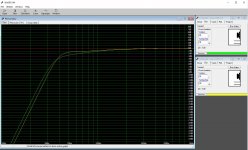
So, I'm thinking, as the first option, that I could buy a cheap hacksaw and shorten the tube. Seas recommends frequencies between 35 and 2500 Hz for this woofer. Currently the port and box are tuned to 34 Hz. WinISD box simulation shows that the woofer would probably benefit from a slightly higher tuning, say 38 Hz (image 1: in green the woofer in the current 24 litre box with 34 Hz tuning; in yellow the woofer in a 24 liter box with 38 Hz tuning). This would also decrease the vent mach from 0,24 to 0,21, so maybe I'd get a bit more punch and less distortion by cutting only slightly the lower end of bass response.
As the second option I could buy an electric drill and a drill bit for making a bigger, say 50 -70 mm, hole and go for a bigger tube diameter. According to WinISD, 68 mm tube diameter with the 34 Hz tuning would require a 33,6 cm long tube. The box is really shallow though, only 20,2 cm deep from the baffle's outer edge to the back panel's inner surface inside the box. Fitting a wider tube would thus require bending/angling the tube. Of course with a higher tuning, say the 38 Hz, a 68 mm tube would be 25,9 cm long, which would be more feasible. A 50 mm tube at 38 Hz would fit the box nicely at 13 cm length instead of the current 12,3 cm. It would also go from the current vent mach 0,24 to 0,16. WinISD has the 0,24 in red and 0,16 in green indicating that it would be more suitable.
Any experience on reflex ports? Would the 38 Hz with the current tube be beneficial enough (or at all), or should I go through the trouble of finding equipment and drilling bigger holes? Any real woodwork is just out of question right now, for I don't have any real option for doing such. In general I'm a bit reluctant to buy any more equipment right now. I could maybe justify to myself buying an electric drill/screwdriver though, for it might be useful in life outside speaker stuff as well.
Attachments
if the port is too small in diameter you will tend to get chuffing (wind) noises. I'm colourblind and cannot tell which curve is which colour, but I assume the one that is flatter and rolling off steeper is the 38Hz tuning one.
You may find that the transient response of the higher tuning frequency is slightly better. What you may be thinking of as distortion could be response ripple (driver taking a long time to come back to rest after an excitation.
Unibox will show step response in one of it's graphs which is a good way of seeing how the driver comes back to rest with different box tunings.
Looks like you are definitely making progress! It's good when things start to fall into place isnt it!!
Tony.
Regarding voicing the speakers in my listening environment: The harsh realities of life force me to put my speakers on a bookshelf at a pretty high position. The shelf they're on is at the height of 133 cm (4.36 feet) and thus the speaker's top panel is at 185 cm (6.06 feet). I've usually had the speakers on the bookshelf upside down (i.e. tweeter below woofer) for to have the tweeter as low as possible (they're usually listened to while sitting on a sofa). Also being forced to place the speakers right next to the wall, less than 20 cm apart from it, makes some pretty heavy low frequencies and is really hideous for the sound stage, but that's yet another topic.
For this new XO configuration I tried the speakers right side up, for some reason. I found it really overly and aggressively bright. I was already thinking about some changes, namely a bigger resistor and a smaller second capacitor, for the tweeter, but still tried them upside down. Very balanced sound! The difference was really a major one.
What I'm thinking is the room acoustics: the painted, hard, stone ceiling is at the height of 2,88 m (9.44 feet). If the speaker is placed "normally" (tweeter up and woofer below), the tweeter is about 1,78 m (5.84 feet) from the floor and 1,13 m (3.71 feet) from the ceiling. Thus the floor reflections one would experience become ceiling reflections via a mercilessly hard stone surface.
If the speaker's upside down, the tweeter is at about 1,41 m (4.62 feet) from the floor and about 1,49 cm (4.89 feet) from the ceiling. There aren't too many rugs on the floor either, but it's made of wood and there's furniture to disperse and redirect reflections. The tweeter's sound that is headed towards the ceiling is from a very steep off axis angle, so there's a lot of attenuation towards high frequencies. Also the tweeter's sound has to go through the "soundfield" produced by the woofer, so there probably is some cancellation before the tweeter's sound can reach the ceiling and reflect to the listener.
if the port is too small in diameter you will tend to get chuffing (wind) noises. I'm colourblind and cannot tell which curve is which colour, but I assume the one that is flatter and rolling off steeper is the 38Hz tuning one.
You may find that the transient response of the higher tuning frequency is slightly better. What you may be thinking of as distortion could be response ripple (driver taking a long time to come back to rest after an excitation.
Unibox will show step response in one of it's graphs which is a good way of seeing how the driver comes back to rest with different box tunings.
Looks like you are definitely making progress! It's good when things start to fall into place isnt it!!
Tony.
You're right, the flatter and steeper roll off belongs to 38 Hz.
The chuffing noises are probably what I'm experiencing. It's especially apparent when I listen to an old favorite on a CD: Erykah Badu's album "Mama's gun". It features some really percussive electric bass playing at really low frequencies (Pino Palladino is a great bass player with some original ideas). I'm constantly getting a feeling that the bass gets really muddled and distorted at low frequencies. For some reason the feeling isn't so bad with the current XO as with some previous ones, but it's still very much there.
The original woofers the speakers featured, Seas P17 RC4, produced overall a bit lower bass response. They also had a bit more moving mass and a bit more power behind the mass, so they probably got around the lower tuning frequency because of that.
I'm thinking I'll just hacksaw a cm or so off the reflex tubes to try it out. There just isn't a real caveat to it as far as I know. The woofers seem to prefer a bit higher tuning anyways. Also the bass response isn't going to dramatically change because of shorter tubes, for the bass response change from 34 to 38 Hz reflex tuning is pretty linear and not drastic at all. The difference in reflex tube length from 34 to 38 Hz would be 3,1 cm, but I'll probably start with just one cm and listen to the result.
It is a very nice thing indeed when things really start to fall into place! Looking back to older measured curves, it shows I'm at a fairly balanced curve now, more so than before. Measurements in a normal room, though, pretty much tell nothing about subtler differences, do they?
There's just something about speakers that deliver music instead of some random audio signal. I'm really feeling the music now for the first time with this (re)design.
Last edited:
You should be able to check the actual tuning frequency with the impedance measurement. See if it is really 34Hz. The tuning frequency is the mid point between the two impedance peaks (and should also be the point where the phase crosses zero). Do it before changing the port, and then after to verify how much you have shifted the tuning frequency I do suspect that the higher tuning will be an improvement. It's all about tradeoffs, you will get slightly less deep bass extention but hopefully a tighter bass.
another way to test it is to slowly sweep a frequency and find the point where the cone is almost still but there is a lot of air coming out of the ports. this should correspond to your tuning freq.
Tony.
I do suspect that the higher tuning will be an improvement. It's all about tradeoffs, you will get slightly less deep bass extention but hopefully a tighter bass. another way to test it is to slowly sweep a frequency and find the point where the cone is almost still but there is a lot of air coming out of the ports. this should correspond to your tuning freq.
Tony.
- Status
- This old topic is closed. If you want to reopen this topic, contact a moderator using the "Report Post" button.
- Home
- Loudspeakers
- Multi-Way
- A daunting first (re)design